Manufacturing method of tooth part, tooth part, and processing device of tooth part

a technology of processing device and tooth part, which is applied in the field of manufacturing method of tooth part, tooth part, and processing device of tooth part, can solve the problems of large load on the open end portion, possible chipping of cutting tools etc., and achieve the effect of easy adjustment, increased rigidity of tooth part, and easy cutting

Active Publication Date: 2020-12-17
AISIN CORP
View PDF0 Cites 1 Cited by
  • Summary
  • Abstract
  • Description
  • Claims
  • Application Information

AI Technical Summary

Benefits of technology

[0006]In the cup-shaped part described in Patent Document 2, since the smooth outer peripheral portion having no thickness reduction is formed on the open end portion side of the outer peripheral surface of the cylindrical portion, it is possible to further improve the strength of the cylindrical portion on the open end portion side, compared to the multi-plate clutch outer drum according to Patent Document 1. However, in the cup-shaped part described in Patent Document 2, the thickness of the open end portion of the cylindrical portion is increased due to the smooth outer peripheral portion being formed. Thus, when the open end portion is cut to adjust the axial length of the cylindrical portion, chipping of the cutting tool etc. may occur due to impact and friction of intermittent cutting. Further, when cutting the open end portion including the smooth outer peripheral portion by plastic working in order to adjust the axial length of the cylindrical portion, a large load needs to be applied to cut the open end portion.Means for Solving the Problem
[0007]An aspect of the disclosure is to allow an axial length of a tubular portion to be easily adjusted while satisfactorily ensuring rigidity of a tooth part including a tubular portion, an inner tooth portion formed on an inner peripheral surface of the tubular portion, and an outer tooth portion formed on an outer peripheral surface of the tubular portion.
[0009]Such a method forms the annular rib that extends in an annular shape on a radially outer side than the inner peripheral wall portions by pushing out the inner peripheral wall portions and the tooth surface portions radially outward while shearing, at the open end of the tubular portion. By forming the annular rib at the open end of the tubular portion in this way, the rigidity of the tooth part can be increased. Further, the thickness of the annular rib is substantially the same as the thickness of the inner peripheral wall portion and the tooth surface portion. Thus, since the annular rib can be easily cut, the axial length of the tubular portion of the tooth part can be easily adjusted. As a result, the axial length of the tubular portion can be easily adjusted while the rigidity of the tooth part is satisfactorily ensured.

Problems solved by technology

Thus, when the open end portion is cut to adjust the axial length of the cylindrical portion, chipping of the cutting tool etc. may occur due to impact and friction of intermittent cutting.
Further, when cutting the open end portion including the smooth outer peripheral portion by plastic working in order to adjust the axial length of the cylindrical portion, a large load needs to be applied to cut the open end portion.

Method used


Image

  • Manufacturing method of tooth part, tooth part, and processing device of tooth part
  • Manufacturing method of tooth part, tooth part, and processing device of tooth part
  • Manufacturing method of tooth part, tooth part, and processing device of tooth part

Examples


Embodiment Construction

[0025]Modes for carrying out the various aspects of the present disclosure will be described below with reference to the accompanying drawings.

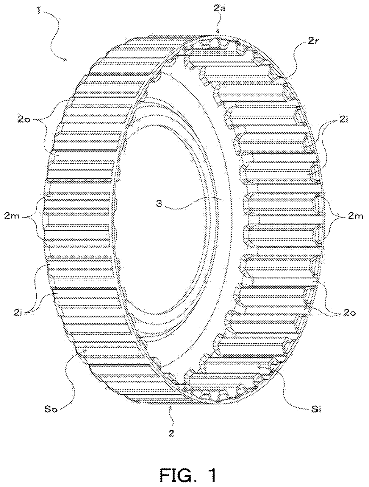
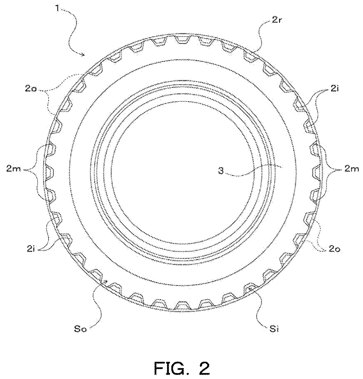
[0026]FIG. 1 is a perspective view illustrating a drum member 1 that is a tooth part of the present disclosure. FIG. 2 is a front view illustrating the drum member 1. The drum member 1 illustrated in FIG. 1 and FIG. 2 is used as a clutch drum of a clutch included in a vehicle transmission (not shown) and a hub of another clutch different from the clutch or a brake. As illustrated, the drum member 1 is formed in a bottomed cylindrical shape with one end opened, and includes a tubular portion 2 and an annular side wall portion (bottom portion) 3 that extends radially inward from an end portion (other end) on the opposite side of the tubular portion 2 from an open end 2a (see FIG. 1). The side wall 3 of the drum member 1 is connected to one of the clutches to be fastened.

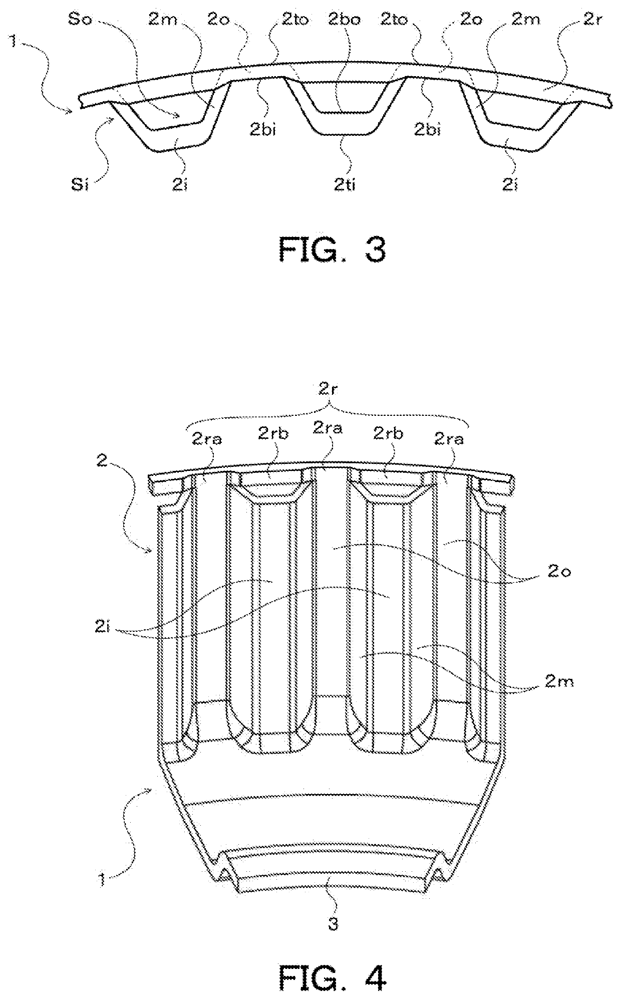
[0027]On an inner peripheral surface of the tubular portion 2, an internal ...


PUM

PropertyMeasurementUnit
annular shapeaaaaaaaaaa
diameteraaaaaaaaaa
circumferenceaaaaaaaaaa

Abstract

The tooth part includes: a tubular portion having an inner tooth portion formed on an inner peripheral surface and an outer tooth portion formed on an outer peripheral surface; a plurality of inner peripheral wall portions that each extend in an axial direction of the tubular portion and form a tooth tip portion of the inner tooth portion and a tooth bottom portion of the outer tooth portion; a plurality of outer peripheral wall portions that each extend in the axial direction and form a tooth bottom portion of the inner tooth portion and a tooth tip portion of the outer tooth portion; and an annular rib that is joined to the outer peripheral wall portions and that extends in an annular shape on an open end side with respect to the inner peripheral wall portions in the axial direction and radially outward from the inner peripheral wall portions, at an open end of the tubular portion.

Description

CROSS REFERENCE TO RELATED APPLICATIONS[0001]This application is a National Stage of International Application No. PCT / JP2019 / 002555 filed Jan. 25, 2019, claiming priority based on Japanese Patent Application No. 2018-015722 filed Jan. 31, 2018 the entire contents of which are incorporated herein by reference.TECHNICAL FIELD[0002]The present disclosure is related to: a manufacturing method of a tooth part including a tubular portion, an inner tooth portion formed on an inner peripheral surface of the tubular portion, and an outer tooth portion formed on an outer peripheral surface of the tubular portion; a tooth part; and a processing device of a tooth part.BACKGROUND ART[0003]Conventionally, as a tooth part, a multi-plate clutch outer drum formed by press working a steel plate is known (for example, see Patent Document 1). The multi-plate clutch outer drum includes an end wall portion, a cylindrical portion (tubular portion) in which one end is connected to an outer peripheral end ...

Claims


Application Information

Patent Timeline
Patent Type & Authority Applications(United States)
IPC IPC(8): F16D13/60B21D53/26
CPCB21D53/26F16D13/60B21D53/28F16D2250/0023B21D37/12B21H5/02B21D15/02B21D37/10B21D22/02F16D13/62
Inventor MATSUMOTO, RYOMARUYAMA, TAKUYA
Owner AISIN CORP
Why Eureka
Try Eureka