
Apparatus and methods for synaptic update in a pulse-coded network

a pulse-coded network and apparatus technology, applied in the field of artificial neural networks, can solve the problems of inefficient access based on post-synaptic index, adversely affecting the accuracy of post-synaptic pulse generation by the unit, and several limitations, so as to reduce memory bus overhead and reduce memory bus overhead

Inactive Publication Date: 2015-09-29
QUALCOMM INC
View PDF93 Cites 5 Cited by
  • Summary
  • Abstract
  • Description
  • Claims
  • Application Information

AI Technical Summary

Benefits of technology

This patent describes a method for reducing memory bus overhead in a computerized network system. The method involves updating the channel based on the time between the current trigger and a previous trigger associated with a node in the system. This updating is done in a single transaction on the memory bus, which helps to minimize the impact on the network. The technical effect of this method is to improve network efficiency and reduce memory bus usage.

Problems solved by technology

When the synaptic data are stored according to the pre-synaptic index, then access based on the post-synaptic index is inefficient.
However, this approach has several limitations.
(2010) does not provide immediate update for the synaptic weights, because the approach waits for the time window to expire before modifying the synaptic weight, thereby adversely affecting the accuracy of post-synaptic pulse generation by the unit.
Existing synaptic update approaches do not provide synaptic memory access mechanisms that are efficient for a large category of spiking neural networks.
Such approaches also do not provide up-to-date synaptic variables for different kind of learning rules, and are limited by the firing rate of the pre-synaptic and post-synaptic units.
Furthermore, existing synaptic weight update schemes are not applicable to different plasticity models, such as the nearest-neighbor, all-to-all etc.

Method used


Image

  • Apparatus and methods for synaptic update in a pulse-coded network
  • Apparatus and methods for synaptic update in a pulse-coded network
  • Apparatus and methods for synaptic update in a pulse-coded network

Examples


Embodiment Construction

[0061]Embodiments of the present invention will now be described in detail with reference to the drawings, which are provided as illustrative examples so as to enable those skilled in the art to practice the invention. Notably, the figures and examples below are not meant to limit the scope of the present invention to a single embodiment, but other embodiments are possible by way of interchange of or combination with some or all of the described or illustrated elements. Wherever convenient, the same reference numbers will be used throughout the drawings to refer to same or like parts.

[0062]Where certain elements of these embodiments can be partially or fully implemented using known components, only those portions of such known components that are necessary for an understanding of the present invention will be described, and detailed descriptions of other portions of such known components will be omitted so as not to obscure the invention.

[0063]In the present specification, an embodi...


PUM


Abstract

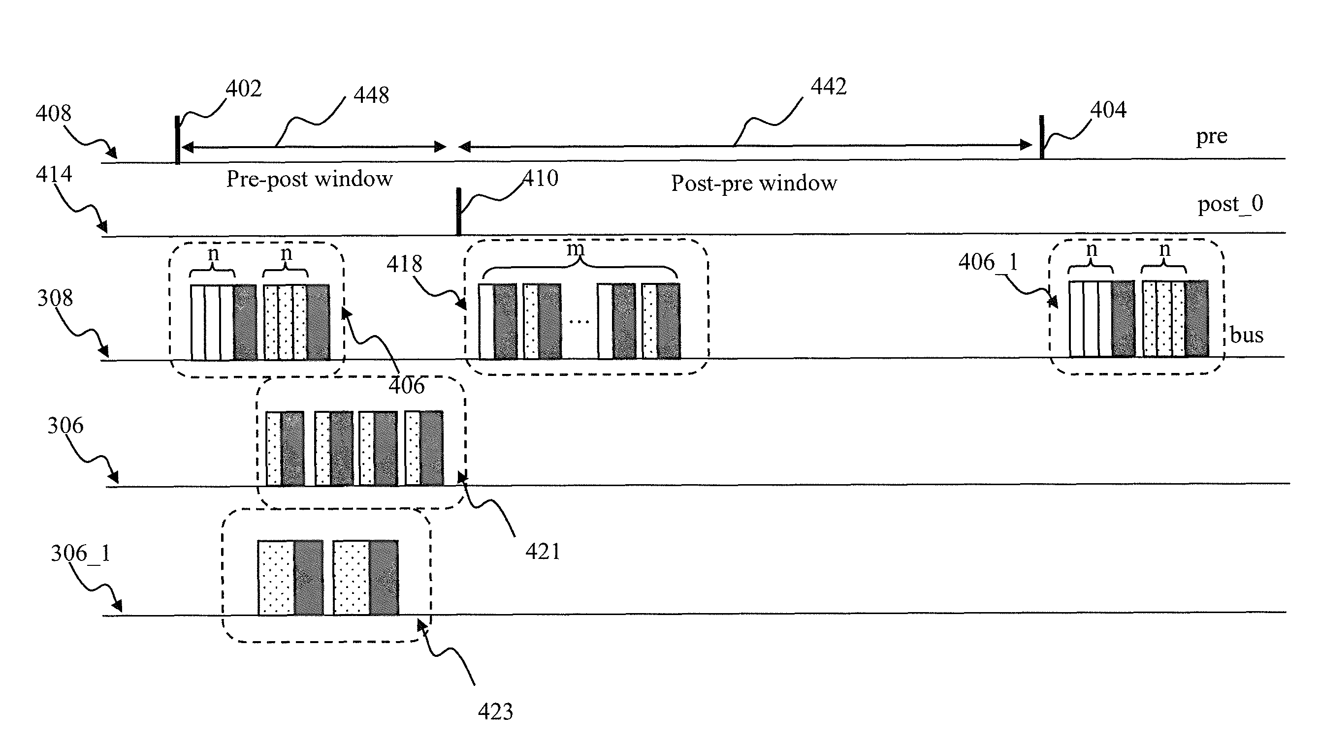
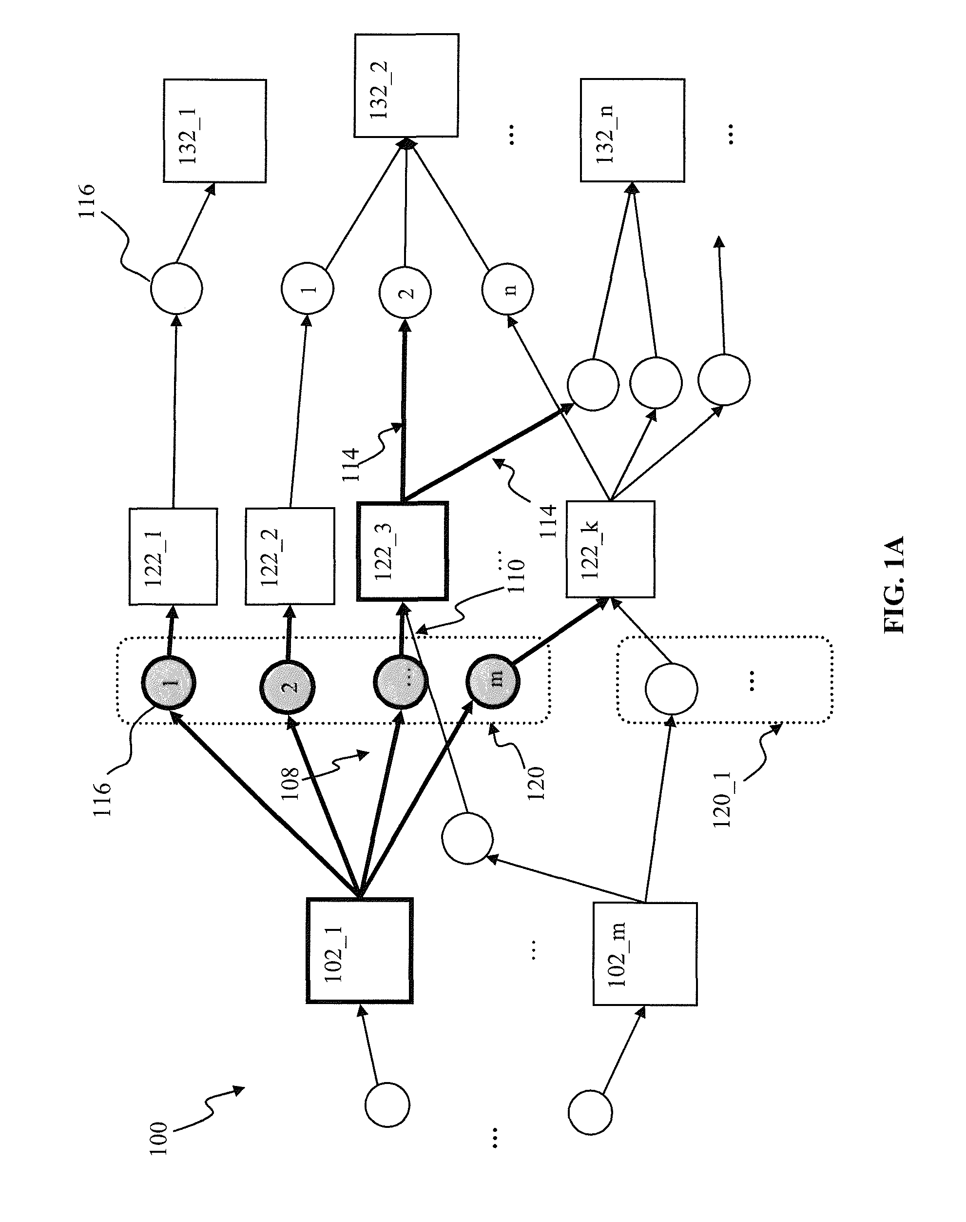
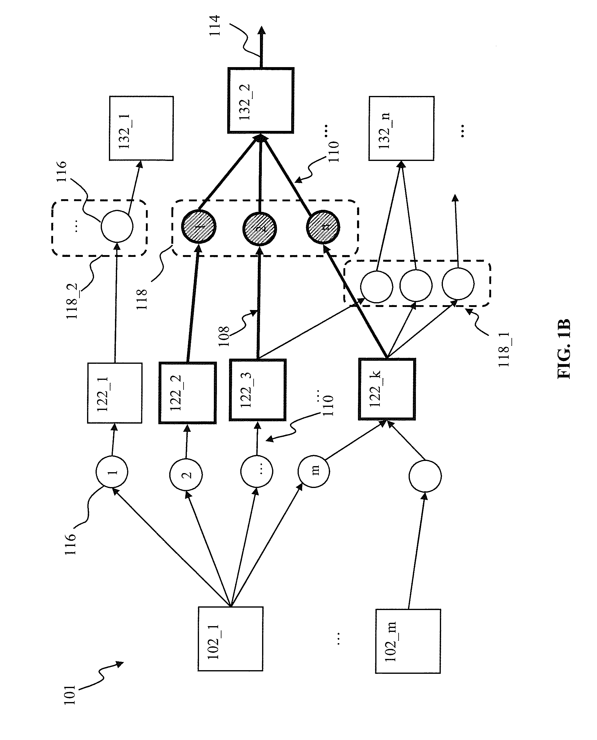
Apparatus and methods for efficient synaptic update in a network such as a spiking neural network. In one embodiment, the post-synaptic updates, in response to generation of a post-synaptic pulse by a post-synaptic unit, are delayed until a subsequent pre-synaptic pulse is received by the unit. Pre-synaptic updates are performed first following by the post-synaptic update, thus ensuring synaptic connection status is up-to-date. The delay update mechanism is used in conjunction with system “flush” events in order to ensure accurate network operation, and prevent loss of information under a variety of pre-synaptic and post-synaptic unit firing rates. A large network partition mechanism is used in one variant with network processing apparatus in order to enable processing of network signals in a limited functionality embedded hardware environment.

Description

CROSS-REFERENCE TO RELATED APPLICATIONS[0001]This application is related to co-owned U.S. patent application Ser. No. 13 / 239,259 filed contemporaneously herewith on Sep. 21, 2011 entitled “APPARATUS AND METHODS FOR PARTIAL EVALUATION OF SYNAPTIC UPDATES BASED ON SYSTEM EVENTS ”, U.S. patent application Ser. No. 13 / 239,123 filed contemporaneously herewith on Sep. 21, 2011 entitled “ELEMENTARY NETWORK DESCRIPTION FOR NEUROMORPHIC SYSTEMS”, U.S. patent application Ser. No. 13 / 239,148 filed contemporaneously herewith on Sep. 21, 2011 entitled “ELEMENTARY NETWORK DESCRIPTION FOR EFFICIENT LINK BETWEEN NEURONAL MODELS AND NEUROMORPHIC SYSTEMS”, U.S. patent application Ser. No. 13 / 239,155 filed contemporaneously herewith on Sep. 21, 2011 entitled “ELEMENTARY NETWORK DESCRIPTION FOR EFFICIENT MEMORY MANAGEMENT IN NEUROMORPHIC SYSTEMS”, U.S. patent application Ser. No. 13 / 239,163 filed contemporaneously herewith on Sep. 21, 2011 entitled “ELEMENTARY NETWORK DESCRIPTION FOR EFFICIENT IMPLEMEN...

Claims


Application Information

Patent Timeline
Patent Type & Authority Patents(United States)
IPC IPC(8): G06F1/16G06N3/04
CPCG06N3/049
Inventor IZHIKEVICH, EUGENE M.PIEKNIEWSKI, FILIPNAGESWARAN, JAYRAM MOORKANIKARALEVIN, JEFFREY ALEXANDERRANGAN, VENKATMALONE, ERIK CHRISTOPHER
Owner QUALCOMM INC
Learn More