
Interferometric systems and methods

a technology of interferometry and optical microscope, applied in the field of optical techniques, can solve the problems of significant decline in the sale of optical microscopes, time-consuming, and evacuating samples

Inactive Publication Date: 2015-07-14
INVENTTECH +1
View PDF68 Cites 1 Cited by
  • Summary
  • Abstract
  • Description
  • Claims
  • Application Information

AI Technical Summary

Benefits of technology

The present invention relates to an improved optical microscope and interferometer that can view, probe, modify, or create small features using the intense, isolated radiation of the atomic Hydrogen resonance line at 121.6 nm. The use of light at this wavelength has several advantages, including a narrow, highly transparent window in the air absorption spectrum and effective transmission of light within optical systems without the need for high vacuum. Furthermore, strong, relatively-monochromatic light sources and optical components can be developed for the Hydrogen Lyman-α line. These improvements contribute to the advancement of optical microscopy and related imaging techniques.

Problems solved by technology

Also, optical microscopy does not involve evaporating coating onto the samples, or evacuating the sample chamber, both of which can be time consuming.
Notwithstanding the advantages of optical microscopes relative to electron microscopes such as those described above, in recent years there has been a significant decline in the sale of optical microscopes.
A number of techniques involving shorter-wavelength light have been considered, yet these techniques suffer from various disadvantages.
For example, while an optical microscope employing light within the near ultraviolet range (approximately 200 nm<λ<400 nm) may provide some wavelength advantage over a visible light optical microscope, the difficulties of image display and aberrations in optical components may not justify that advantage.
However, it is difficult energetically to dissociate Nitrogen and then form the N+6 ion in an electronically excited state.
Indeed, to perform such a process and thereby generate light at the desired wavelength, complicated methods and equipment such as pinched plasma sources and high-powered pulsed lasers are necessary.
Implementation of a microscope in a manner such that light is transmitted within a high vacuum, however, can be challenging and costly.
Again with respect to the semiconductor industry more particularly, cost-effective, high throughput optical mask inspection below the 32 nm node is on the verge of resolution and practicality limits, and it has been predicted that progression into sub-32 nm half-pitch in 2015 (sub-128 nm at the mask), even if manufacturable at the wafer level with advanced processing techniques, presents a difficult challenge for the photomask industry.
While sources at extreme ultraviolet (EUV) wavelengths (e.g., 13 nm) have been attempted, these options still appear to present a risk of high cost and complications.

Method used


Image

  • Interferometric systems and methods
  • Interferometric systems and methods
  • Interferometric systems and methods

Examples


Embodiment Construction

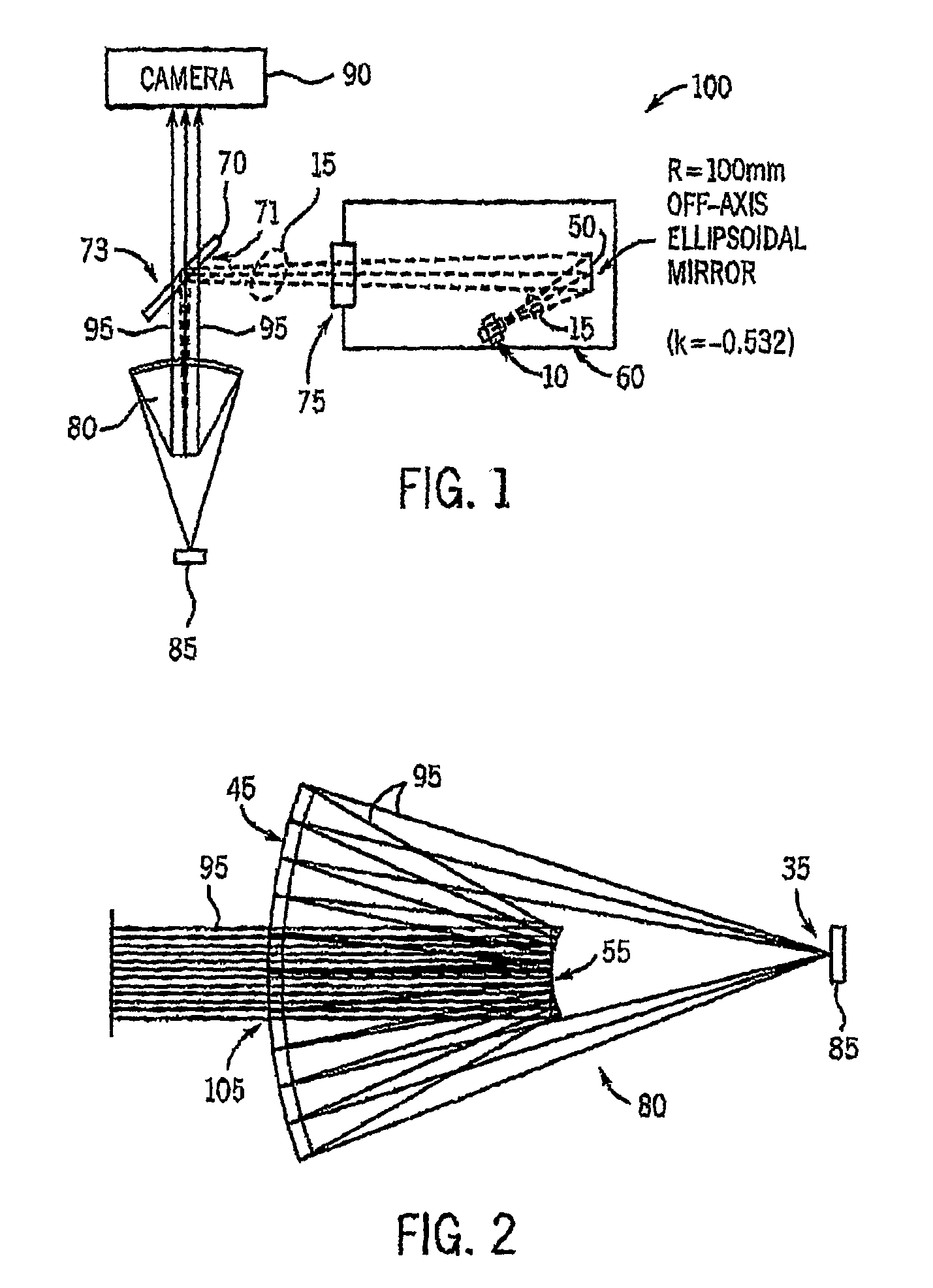
[0035]FIG. 1 illustrates, in simplified schematic form, exemplary components of an optical microscope 100, in accordance with at least one embodiment of the present invention. As will be described in further detail below, the optical microscope 100 operates through the use of light at the Hydrogen Lyman-α line, that is, light at (or approximately at) a wavelength of 121.6 nm. This wavelength is in the “vacuum ultraviolet” and “deep ultraviolet” regions of the electromagnetic spectrum, which generally overlap one another, albeit the vacuum ultraviolet region is generally understood to extend from the region of strong absorption by molecular Oxygen near about 190 nm (or alternatively near about 185 nm) to the “Soft” X-ray region near 20 nm while the deep ultraviolet region is generally understood to extend to wavelengths somewhat higher than 190 nm (e.g., up to nearly 200 (e.g., 193) or 250 (e.g., 248) nm. Further as will be described below, utilization of light at the Hydrogen Lyman-...


PUM

PropertyMeasurementUnit
wavelengthaaaaaaaaaa
path lengthaaaaaaaaaa
feature sizeaaaaaaaaaa

Abstract

Optical systems and methods including interferometric systems and methods are disclosed herein. In some embodiments, the present invention relates to a system comprising at least one light source including a deep ultraviolet light source, a lens device, a beam splitter, and a camera device. The lens device receives first light, directs at least some of that light toward a target location, receives reflected light therefrom, and directs at least some of the reflected light toward a further location, where at least part of a light path between the deep ultraviolet light source and the target location is other than at a high vacuum. The camera device is positioned at either the further location or an additional location, whereby an image is generated by the camera device based upon at least a portion of the reflected light. Also encompassed herein are interferometric lithography and optical microscopy systems.

Description

CROSS-REFERENCE TO RELATED APPLICATIONS[0001]This application is a continuation-in-part of, and claims the benefit of, U.S. utility patent application Ser. No. 12 / 304,494 filed on Dec. 12, 2008 and entitled “Apparatus and Method for Deep Ultraviolet Microscopy”, which is the U.S. national phase of PCT patent application no. PCT / US2007 / 071003 filed on Jun. 12, 2007 and entitled “Apparatus and Method for Deep Ultraviolet Microscopy”, which in turn claims priority to U.S. provisional patent application No. 60 / 812,912 filed on Jun. 13, 2006 and entitled “Method and Apparatus for Deep Ultraviolet Microscopy”, each of which is hereby incorporated by reference herein.STATEMENT REGARDING FEDERALLY SPONSORED RESEARCH OR DEVELOPMENT[0002]N / AFIELD OF THE INVENTION[0003]The present invention relates to optical techniques such as optical microscopy and / or interferometry and, more particularly, to such optical techniques that employ light at wavelengths outside of the visible light spectrum.BACKG...

Claims


Application Information

Patent Timeline
Patent Type & Authority Patents(United States)
IPC IPC(8): G02B21/16G01N21/45G01J3/02G01J3/453G01J3/10
CPCG02B21/16G01J3/0208G01J3/10G01J3/453G01N21/45G01N2021/451
Inventor GELERNT, BARRYMILSTER, THOMAS D.JOTA, THIAGO
Owner INVENTTECH
Learn More