
Case hardening steel, carburized component, and manufacturing method of case hardening steel

a manufacturing method and hardening technology, applied in the direction of manufacturing tools, furnaces, heat treatment equipment, etc., can solve the problems of further degradation of machinability, difficult application of such techniques to industrial use, and reduced machining accuracy, so as to reduce the degradation of dimensional accuracy, reduce the degradation of machining accuracy, and suppress the coarse grain at the time of carburizing.

Inactive Publication Date: 2015-03-17
NIPPON STEEL CORP
View PDF19 Cites 3 Cited by
  • Summary
  • Abstract
  • Description
  • Claims
  • Application Information

AI Technical Summary

Benefits of technology

The case hardening steel described in this patent improves fatigue strength and reduces degradation in dimensional accuracy by suppressing grain coarsening during carburizing. It enables cold forging of components that were previously difficult due to coarse grains and reduces the need for annealing after cold forging. Additionally, it prevents the production of coarse grains during high-temperature carburizing, resulting in sufficient strength properties such as rolling contact fatigue. The steel also provides favorable cutting workability, making it easier to machine and cut.

Problems solved by technology

However, as a result, a problem of degraded machinability is posed, making it difficult for such techniques to be applied to industrial use.
On the other hand, in the case of increasing the carbon amount in base materials for shortening the carburizing time, there is apprehension that further degradation in machinability will be caused.
Therefore, it is difficult for the techniques to be applied in an actual use.

Method used


Image

  • Case hardening steel, carburized component, and manufacturing method of case hardening steel
  • Case hardening steel, carburized component, and manufacturing method of case hardening steel

Examples


example 1

[0084]Hereunder is a description of examples of the present invention.

[0085]Steel smelting in a converter furnace with a composition shown in Table 1 was subjected to a continuous casting, and was subjected to a cogging step if required, and prepared into a rolled base material which is 162 mm square. Subsequently, steel bars with 24 to 30 mm in diameter were manufactured by hot rolling.

[0086]

TABLE 1SteelCategoryNo.CSiMnPSAlTiNCrMoNiVBNbOComparative steel10.250.230.700.0130.0110.0550.0950.00401.06—————0.0016Comparative steel20.210.250.820.0100.0150.0890.1510.00391.09————0.0290.0018Inventive steel30.230.230.700.0110.0300.1200.0940.00371.07—————0.0013Inventive steel40.240.210.740.0150.0140.1500.1200.00321.240.17————0.0013Inventive steel50.200.190.720.0140.0130.1100.1240.0036—0.19————0.0017Inventive steel60.200.190.830.0130.0140.1980.0590.00750.42—————0.0013Comparative steel70.210.250.700.0140.0110.0650.0780.00341.23—————0.0018Inventive steel80.210.210.790.0120.0140.1240.0600.00661.12—...

example 2

[0101]From a part of the rolled base material, used in Example 1, which was 162 mm square with the composition shown in Table 1, steel bars with a diameter of 70 mm were manufactured by hot rolling. With the steel bars used as base materials, hot forging was performed to finish the steel bars into hot forged members with a diameter of 40 mm. The heating temperatures for the hot forging were 1100° C. to 1290° C.

[0102]The hot forged members manufactured in the aforementioned step were subjected to a normalizing treatment in the condition of heating at 900° C.×1 hour and air-cooling. After that, a carburizing simulation was performed in the condition of heating for 5 hours, and an austenite coarse grain producing temperature was found, in the similar manner with Example 1.

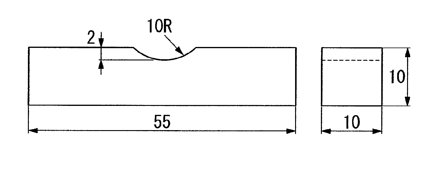
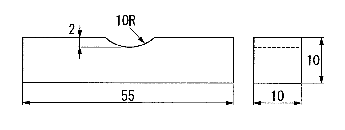
[0103]Furthermore, after the above hot forged member was normalized, a rolling contact fatigue test piece with a diameter of 12.2 mm and a Charpy impact test specimen with a 10R-notch as shown in FIG. 1 were fabricate...


PUM

PropertyMeasurementUnit
diameteraaaaaaaaaa
temperatureaaaaaaaaaa

Abstract

This case hardening steel has a chemical composition including, by mass %: C: 0.1 to 0.6%; Si: 0.02 to 1.5%; Mn: 0.3 to 1.8%; P: 0.025% or less; S: 0.001 to 0.15%; Al: over 0.05 to 1.0%; Ti: 0.05 to 0.2%; N: 0.01% or less; and O: 0.0025% or less, and further including, by mass %, one or more of Cr: 0.4 to 2.0%, Mo: 0.02 to 1.5%, Ni: 0.1 to 3.5%, V: 0.02 to 0.5%, and B: 0.0002 to 0.005%, and the balance consisting of iron and unavoidable impurities.

Description

BACKGROUND OF THE INVENTION[0001]1. Field of the Invention[0002]The present invention relates to a case hardening steel superior in property of preventing coarse grains at the time of carburizing and in fatigue property, and a manufacturing method thereof.[0003]Priority is claimed on Japanese Patent Application No. 2009-008174, filed on Jan. 16, 2009, the contents of which are incorporated herein by reference.[0004]2. Description of Related Art[0005]For gears, bearing components, rolling components, shafts, and constant velocity joints, a medium carbon alloy steel for machine structural purposes, as defined, for example, in JIS G 4052, JIS G 4104, JIS G 4105, JIS G 4106, or the like in Japanese Industrial Standards (JIS), is typically used. These components are typically manufactured through steps of being worked into a predetermined shape by cold forging (including rolling) or hot forging, and cutting, and then carburizing and quenching. In cold forging, products have a good surfac...

Claims


Application Information

Patent Timeline
Patent Type & Authority Patents(United States)
IPC IPC(8): C21D9/52C22C38/44C22C38/08C21D9/00C21D8/02C22C38/22C23C8/20C23C8/24C23C8/30C23C8/26C23C8/32C22C38/00B21J1/02C21D1/32C21D1/58C21D6/00C21D9/32C21D9/36C21D9/38C21D9/40C22C38/02C22C38/04C22C38/06C22C38/28F16C33/62
CPCC21D9/32C21D8/0257C21D9/38C21D9/40C22C38/001C22C38/002C22C38/04C22C38/06C22C38/28F16C33/62C22C38/02B21J1/02C21D6/002C21D8/0205C21D8/0226C21D9/36C21D1/32C21D1/58C21D2211/005C21D2211/004C22C38/58
Inventor MIYANISHI, KEIHASHIMURA, MASAYUKIKOZAWA, SHUUJIKUBOTA, MANABUOCHI, TATSURO
Owner NIPPON STEEL CORP
Learn More