
Packet receiving and transmitting method

a packet and transmission method technology, applied in the field of packet transmitting method and packet receiving method, can solve the problems of packet loss and time delay, packet is unnecessarily retransmitted to the mobile station, and the mobile station cannot receive the retransmitted packet, so as to reduce or prevent the loss of packets and transmission delay

Inactive Publication Date: 2014-11-18
ELECTRONICS & TELECOMM RES INST +1
View PDF33 Cites 0 Cited by
  • Summary
  • Abstract
  • Description
  • Claims
  • Application Information

AI Technical Summary

Benefits of technology

This approach reduces packet loss and transmission delay by accurately identifying packet types and preventing redundant transmissions, thereby optimizing resource usage in OFDMA systems.

Problems solved by technology

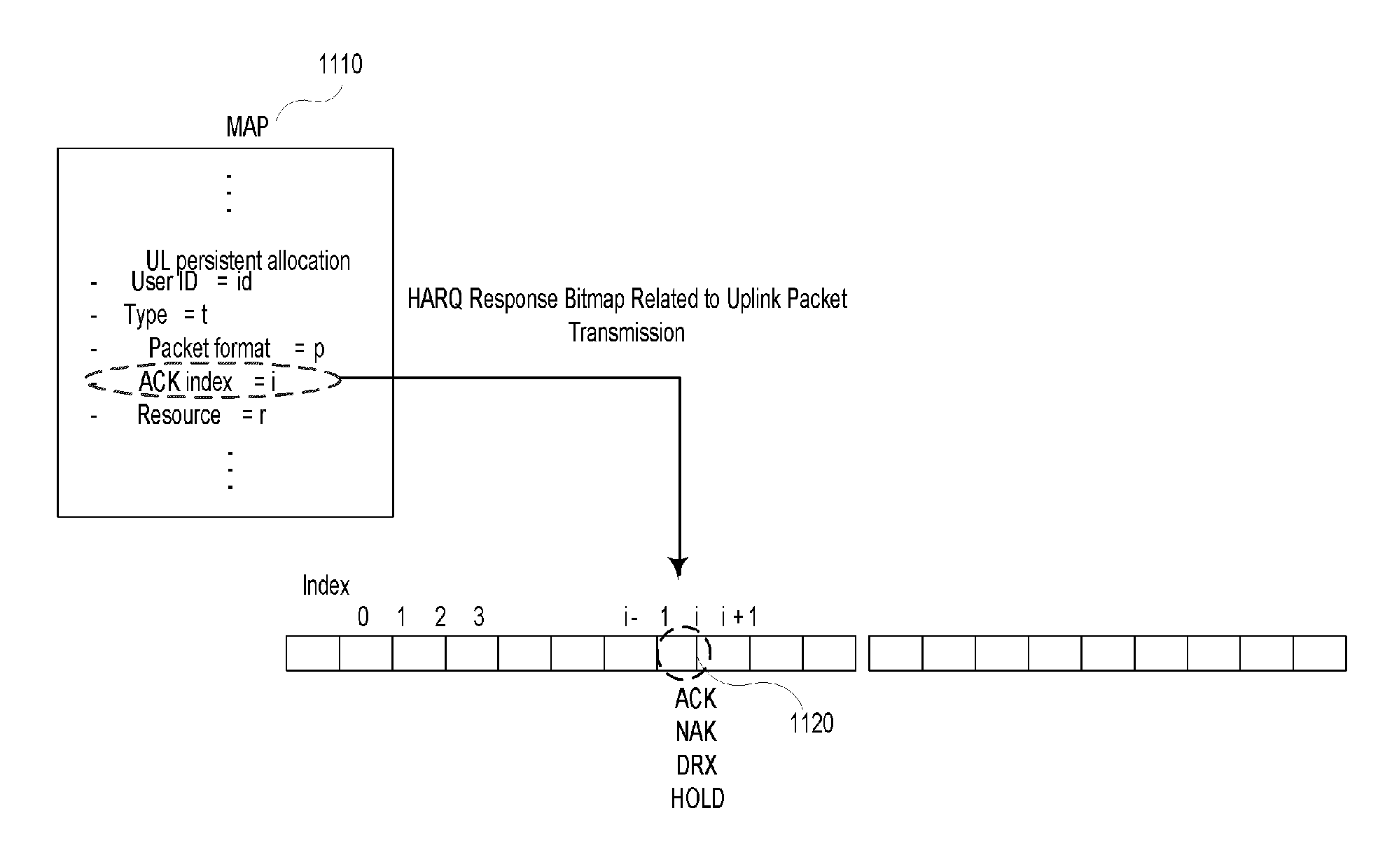
However, in the related art, when a fixedly allocated radio resource is used to transmit packets, the loss of packets and time delay occur due to errors in the detection of an HARQ response signal.
For example, it is assumed that a mobile station successfully receives a packet transmitted from a base station according to the HARQ protocol in a downlink, and transmits an acknowledgement (ACK) in response to the reception of the packet; however, the base station misidentifies the acknowledgement (ACK) as a negative acknowledgement (NAK) due to errors in the detection of the response signal.
However, when errors occur in the detection of the response signal, the base station is likely to misidentify the acknowledgement (ACK) signal from the mobile station as a negative acknowledgement (NAK) signal.
Therefore, the packet is unnecessarily retransmitted to the mobile station, and the mobile station fails to receive the retransmitted packet.
For this reason, in the related art, the method of transmitting packets using a fixedly allocated radio resource according to the HARQ protocol has problems in that packets are redundantly retransmitted between the base station and the mobile station due to errors in the detection of a response signal, which results in the consumption of radio resources.

Method used


Image

  • Packet receiving and transmitting method
  • Packet receiving and transmitting method
  • Packet receiving and transmitting method

Examples


Embodiment Construction

[0028]In the following detailed description, only certain exemplary embodiments of the present invention have been shown and described, simply by way of illustration. As those skilled in the art would realize, the described embodiments may be modified in various different ways, all without departing from the spirit or scope of the present invention. Accordingly, the drawings and description are to be regarded as illustrative in nature and not restrictive. Like reference numerals designate like elements throughout the specification.

[0029]Meanwhile, it will be understood that the terms “comprises” and / or “comprising,” when used in this specification, specify the presence of stated features, integers, steps, operations, elements, and / or components, but do not preclude the presence or addition of one or more other features, integers, steps, operations, elements, components, and / or groups thereof.

[0030]Further, the term “module” used in this specification means a unit for performing a sp...


PUM


Abstract

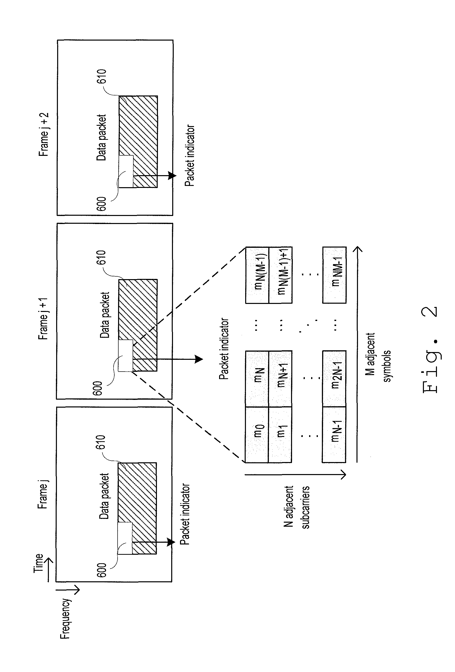
An embodiment of the invention provides a method of receiving packets from a transmitting station at a receiving station in a mobile communication system. The packet receiving method includes receiving a radio resource including a data packet and a packet indicator related to the data packet, identifying the packet indicator, and processing the data packet according to the content of the packet indicator. Another embodiment of the invention provides a method of transmitting packets from a transmitting station to a receiving station in a mobile communication system. The packet transmitting method includes receiving a response signal of a first data packet from the receiving station, allocating a second data packet to a radio resource according to the response signal, allocating a packet indicator related to the second data packet to the radio resource, and transmitting the second data packet and the packet indicator to the receiving station.

Description

TECHNICAL FIELD[0001]The present invention relates to a packet transmitting method and a packet receiving method. More particularly, the present invention relates to a method of transmitting packets between a base station and a mobile station that is capable of reducing a loss of packets and transmission delay due to errors in a hybrid automatic repeat request (HARQ) response signal in an orthogonal frequency division multiplexing access (OFDMA) mobile communication system using a fixedly allocated radio resource.BACKGROUND ART[0002]A base station fixedly allocates radio resources in frames to a mobile terminal that periodically generates traffic.[0003]For example, the fixed allocation of radio resources is included in an IEEE 802.20 draft standard (IEEE P802.20 / D2.1 Draft Standard for Local and Metropolitan Area Networks—Standard Air Interface for Mobile Broadband Wireless Access Systems Supporting Vehicular Mobility—Physical and Media Access Control Layer Specification).[0004]The ...

Claims


Application Information

Patent Timeline
Patent Type & Authority Patents(United States)
IPC IPC(8): H04L1/18H04L1/16H04W28/18H04W28/04
CPCH04L1/1614H04W28/18H04L1/1812H04W28/04H04L1/16H04L9/40
Inventor LIM, KWANG-JAEYOON, CHUL-SIK
Owner ELECTRONICS & TELECOMM RES INST
Learn More