Separator apparatus for separating oil and water

a technology of separator and oil tank, which is applied in electrostatic separation, water/sludge/sewage treatment, centrifuges, etc., can solve the problems of oil and water layer volume in the settling vessel, emulsion layer tends to build up, and the separation is particularly problematic. , to achieve the effect of reducing performan

Inactive Publication Date: 2014-07-15
NOV PROCESS & FLOW TECH AS
View PDF9 Cites 5 Cited by
  • Summary
  • Abstract
  • Description
  • Claims
  • Application Information

AI Technical Summary

Benefits of technology

The patent describes a CEC (Coalescing Electrostatic Apparatus) which improves the separation of oil and water in emulsions. It is effective in coalescing droplets in emulsions of all oil / water ratios, including those that are difficult to separate using gravity separation. The CEC allows a stream of larger droplets to be fed back into the settling vessel, enhancing the separation process. The CEC uses electrically isolated electrodes, making it suitable for offshore or sub-sea processing due to its compact design. Additionally, the CEC can be easily isolated for maintenance without interrupting the flow stream from the well, ensuring continued operation of the settling vessel.

Problems solved by technology

Although oil and water are immiscible liquids, separation is particularly problematic when the water is carried in the form of small droplets in a continuous oil phase.
Furthermore, in these situations the emulsion layer tends to build up over time, further retarding the separation process and reducing the volume of oil and water layers in the settling vessel.
A hydrocyclone may be effective in aiding separation of oil droplets from a water-continuous emulsion, but has a problem in that it is only effective over a limited range of oil / water proportions.
Also hydrocyclones are not effective in separating water droplets in oil-continuous emulsions.
Another problem with using a hydrocyclone is that although some degree of separation and coalesecence of droplets may be achieved, much of this is destroyed at the outlet where the shear forces tend to remix the liquid phases.
Even when there is little or no emulsion layer between the oil and water layers, the size of the settling vessel is limited by practical or economic constraints such that the fluids have insufficient residence time in the vessel for the smallest water droplets to drop out of the oil.

Method used


Image

  • Separator apparatus for separating oil and water
  • Separator apparatus for separating oil and water
  • Separator apparatus for separating oil and water

Examples


Embodiment Construction

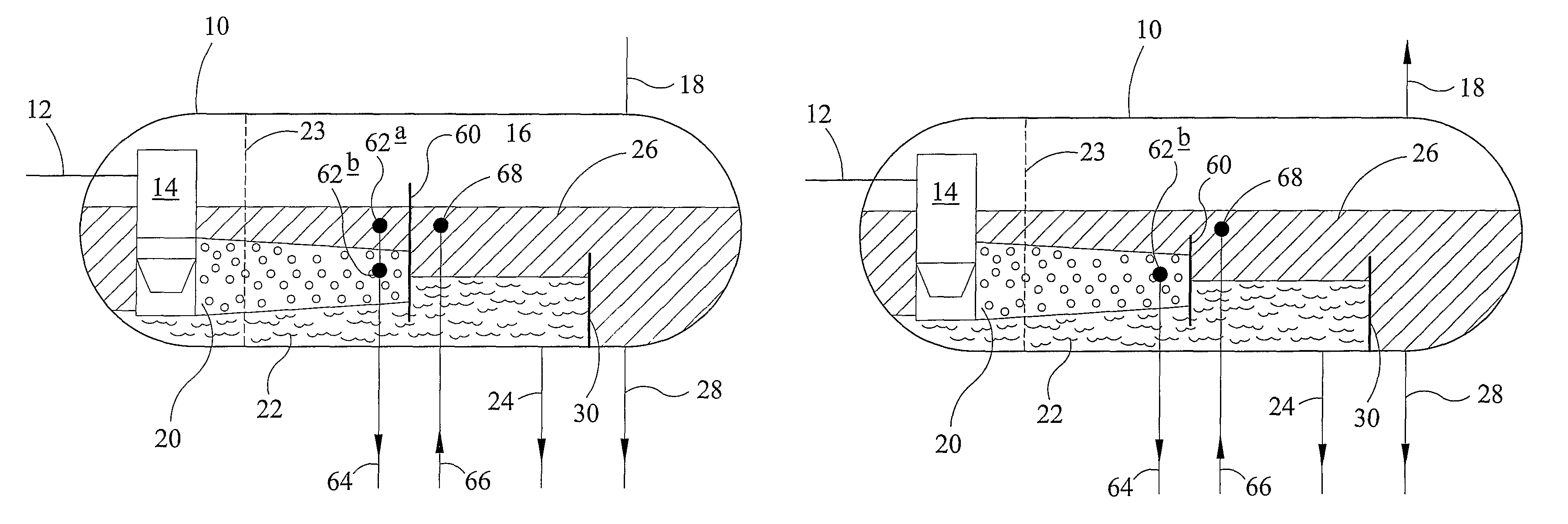
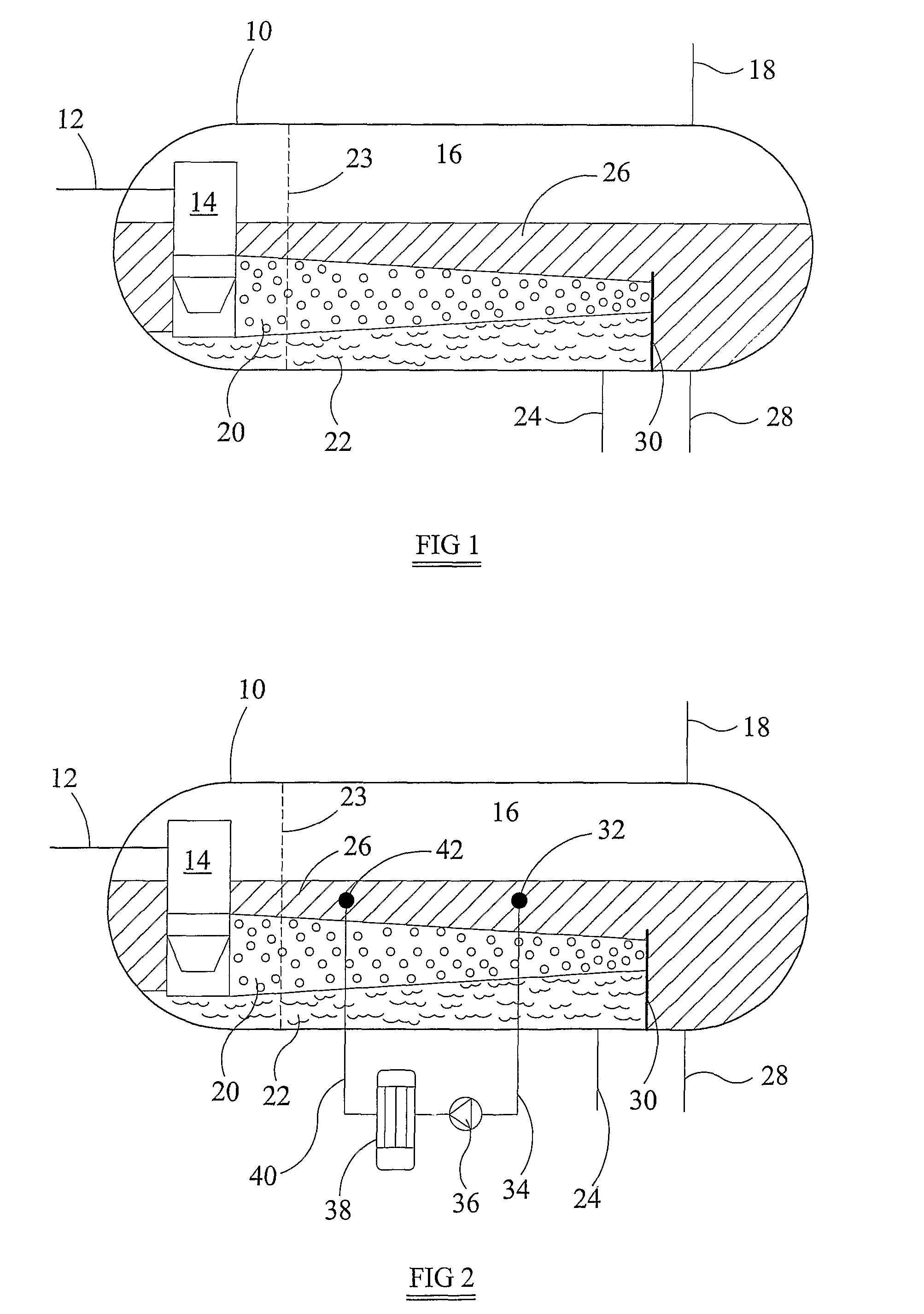
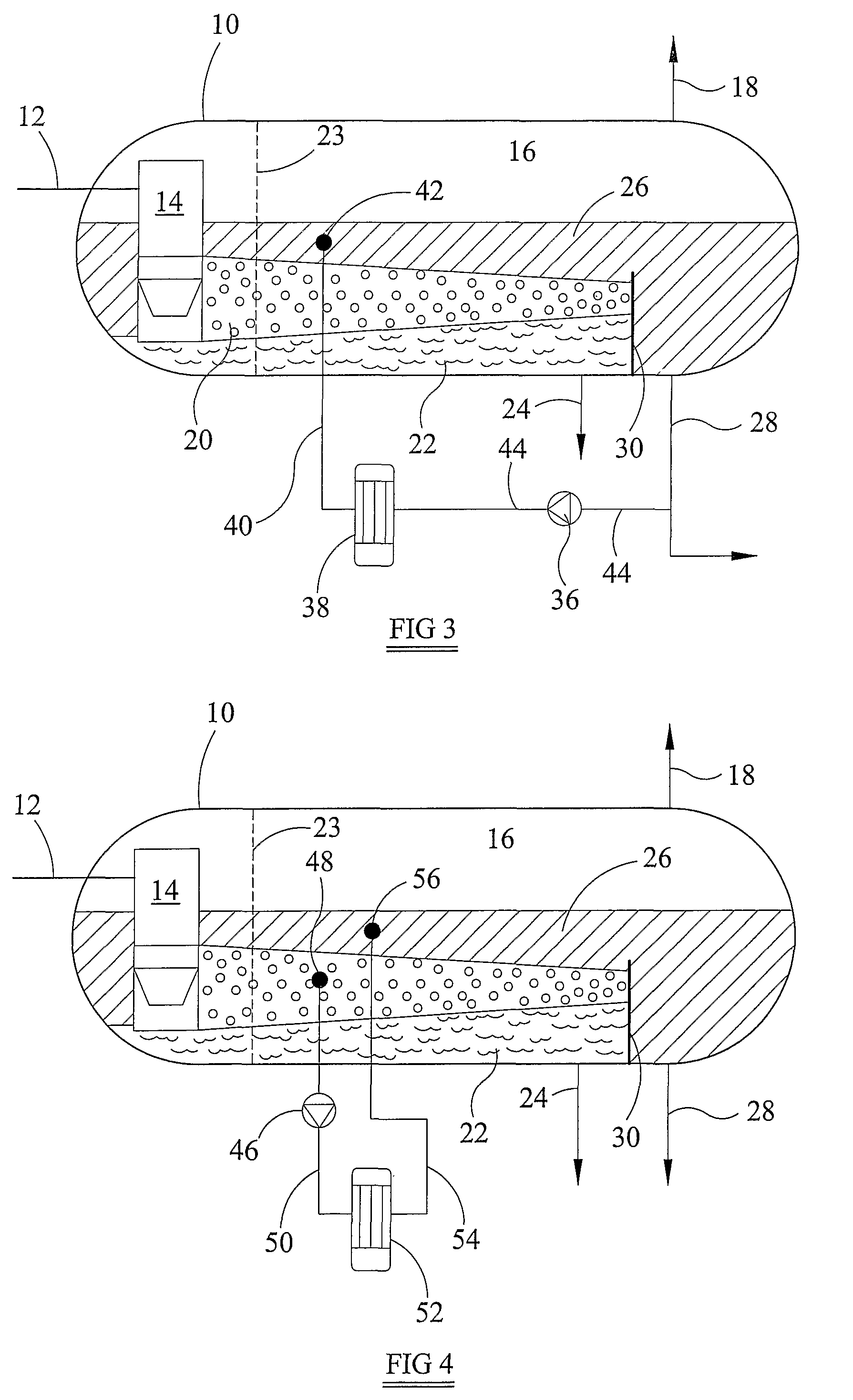
[0031]Referring to FIG. 1, a gravity settling vessel 10 has an inlet 12 for receiving a well-stream. The well stream includes crude oil, water and gas. The well-stream is fed to an inlet cyclone 14 which separates the gas from the other constituents. The gas enters a space 16 at the top of the settling vessel 10 and leaves the vessel by way of a gas outlet 18. The oil and water leave the inlet cyclone 14 as a mixture 20. The mixture 20 most often consists of water in the form of droplets carried by a continuous oil phase. Provided the water droplets are large enough they fall under gravity to the bottom the settling vessel 10 to form a water layer 22. The mixture 20 forms a region or layer between the water layer 22 and an oil layer 26. The oil layer 26 is predominantly crude oil, but contains small droplets of water.

[0032]The water layer 22, oil layer 26, and the mixture 22 move away from the inlet cyclone 14. A distributor plate 23 helps to distribute the flow over the whole of th...


PUM

PropertyMeasurementUnit
Flow rateaaaaaaaaaa
Areaaaaaaaaaaa
Heightaaaaaaaaaa

Abstract

A method of separating oil and water in a flow-stream through a gravity settling vessel (10) in which the flow-stream (12) separates into a lower water layer (22) and an upper oil layer (26), includes feeding an off-take stream (34) of the oil layer and / or an emulsion layer (20) that forms between the oil layer and the water layer through a compact electrostatic coalescer (CEC) (38) that has electrically isolated electrodes. The CEC coalesces water droplets in the off-take stream, and the coalesced off-take stream is then returned to the settling vessel. An associated separator apparatus for comprises: a gravity settling vessel (10); a CEC (38) including electrically isolated electrodes; a coalescer feed line (34) configured to provide an off-take stream of an oil phase and / or an emulsion layer from the settling vessel to the CEC; and a return line (40) from the CEC for returning the off-take stream to the settling vessel.

Description

CROSS-REFERENCE TO RELATED APPLICATIONS[0001]This application is a national stage of, claims priority to and the benefit of, and incorporates herein by reference in its entirety International (PCT) Patent Application No. PCT / IB2005 / 003263, which was filed on Sep. 9, 2005 and which claimed priority to and the benefit of Great Briton Patent Application No. 0419994.9, filed on Sep. 9, 2004 and also incorporated herein by reference in its entirety.BACKGROUND OF THE INVENTION[0002]The present invention relates to a method and apparatus for improving the performance of a separator. More particularly the invention relates to a method and apparatus for improving the performance of a separator used for separating crude oil and water in oil production well-streams.[0003]The production well-stream from an oil well may contain a mixture of oil and water (and may also include gases, solids and other fluids). The water may arise naturally, or may be a result of water (e.g. seawater) pumped into t...

Claims


Application Information

Patent Timeline
IPC IPC(8): C10G33/02B01D17/028
CPCB03C5/02B01D17/06B01D19/0057B03C11/00B03C2201/02C10G33/02B01D17/0211
Inventor LIVERUD, JONGULBRAAR, ARNE MYRVANGDAVIES, SIMON
Owner NOV PROCESS & FLOW TECH AS
Why Eureka
Try Eureka