Method of Configuring Cathodes of an Aluminum Reduction Cell

Inactive Publication Date: 2012-11-08
CHINA ALUMINUM INT ENG CORP
View PDF1 Cites 2 Cited by
  • Summary
  • Abstract
  • Description
  • Claims
  • Application Information

AI Technical Summary

Benefits of technology

[0004]An object of the present invention is to provide a method of configuring cathodes of an aluminum reduction cell, which takes the way of staggering high and low cathodes while chamfering at both ends on top surfaces of the high cathode or ramming chamfers thereon with inter-cathode paste. The method is capable of saving investment costs greatly, improving energy saving effect, achieving good stability of the aluminum reduction cell, so as to save energy and reduce energy consumption, thereby overcoming shortages in the prior art.
[0008]chamfering top surfaces of the high cathode blocks or ramming chamfers at both sides of top portions of the high cathode blocks by inter-cathode carbon paste, wherein the chamfers are bevels, round corners or other shaped chamfers so as to improve choking effect, and wherein a depth of the chamfers is not greater than a height difference between the high cathode blocks and the low cathode blocks;
[0013]In comparison with the prior art, the present invention do not process the existing cathode carbon blocks to a great extent. It only staggers the cathode carbon blocks according to their different heights, and only partly chamfers and grooves the high cathode carbon blocks. The purpose of such a configuration is to overcome the vortex produced by the existing cathode carbon blocks and to lower the height of a molten aluminum-electrolyte interface. Through calculation analyses and onsite tests, the effect of choking resulted from chamfering the high cathode (or ramming chamfers with inter-cathode paste) is much better than the case without chamfering. The high and low cathode blocks are made of such a material as anthracite carbon blocks, semi-graphitic carbon blocks or semi-graphitized or graphitized carbon blocks. All of the above manufacturing materials are the materials used for manufacturing the existing cathode carbon blocks, thus no other special materials are needed, and thereby the present invention would not spend much money. Moreover, the present invention also has the advantages of less modification to the reduction cell, good energy saving effect, etc. and has excellent economic benefits, popularization values and use values.

Problems solved by technology

However, there is relative great disparity in terms of energy saving and energy consumption reduction compared with the international advanced level.
However, most of those patents need to add an expensive investment.
Some patents take the way of arranging high and low cathodes, but these arranging ways only simply arrange the high and low cathodes together without handling the shapes of cathodes, the energy saving effect is not notable in view of computer analysis result and practical production.

Method used


Image

  • Method of Configuring Cathodes of an Aluminum Reduction Cell
  • Method of Configuring Cathodes of an Aluminum Reduction Cell
  • Method of Configuring Cathodes of an Aluminum Reduction Cell

Examples


embodiment 1

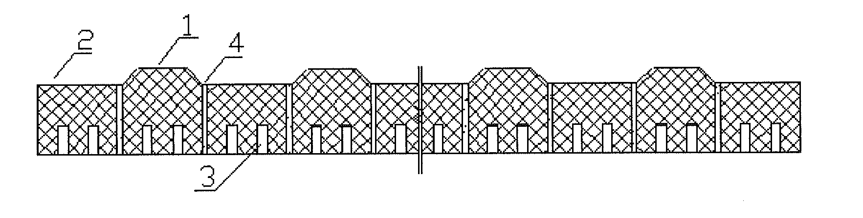
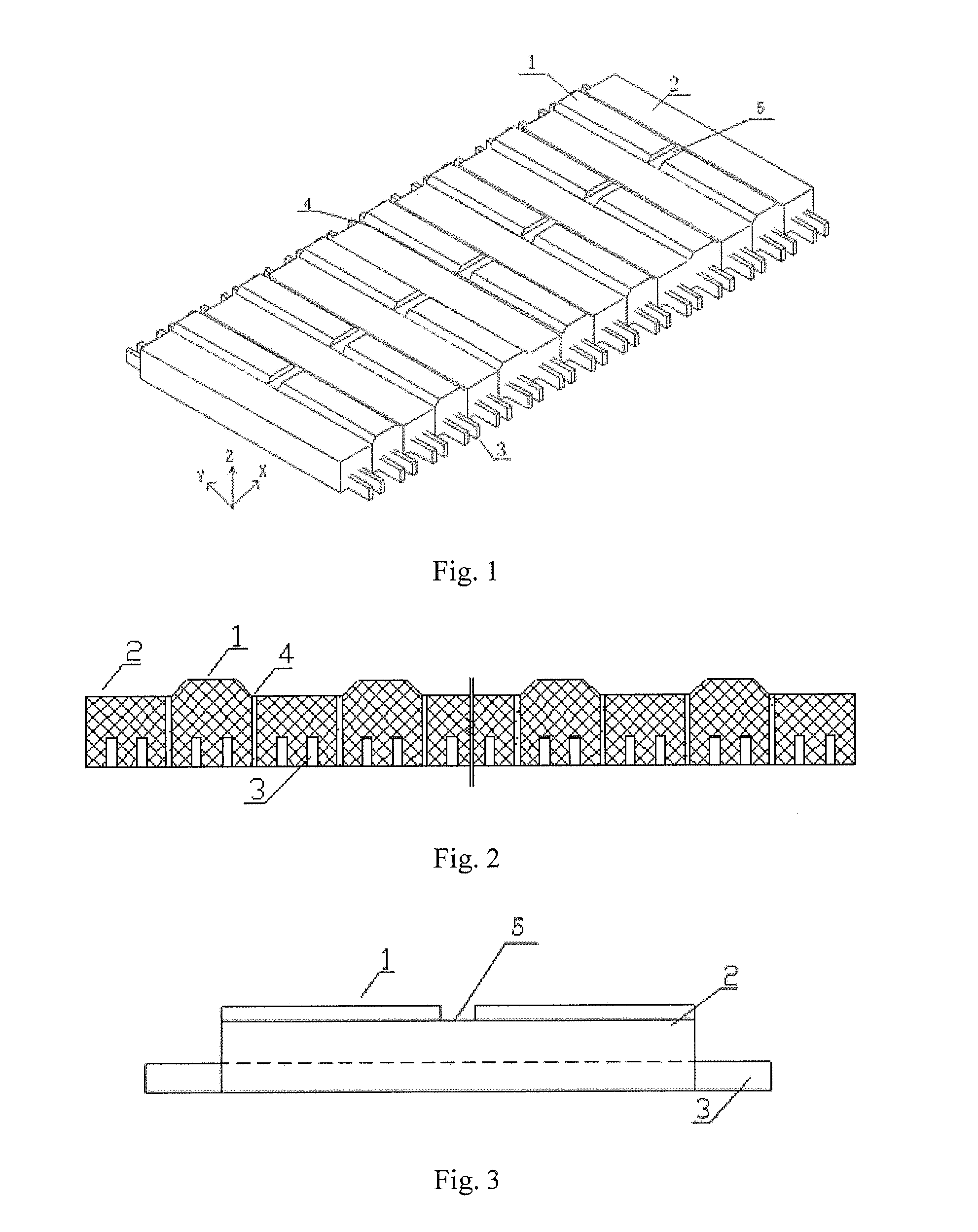
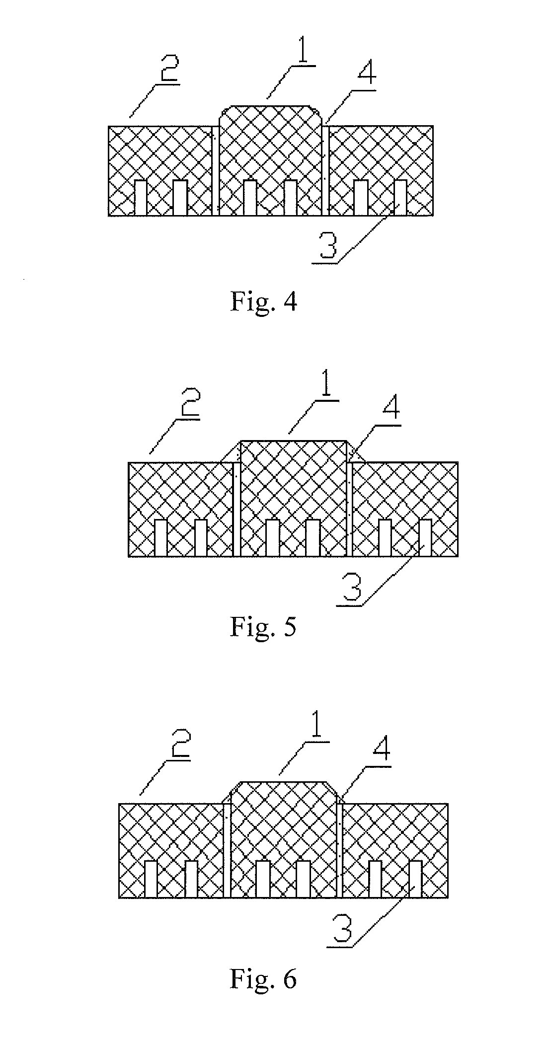
[0020] as shown in FIG. 1, cathode carbon blocks comprise high cathode blocks 1 and low cathode blocks 2. The cathode carbon blocks are disposed at the bottom of an aluminum reduction cell. Cathode steel rods 3 are disposed at bottom surfaces of the cathode carbon blocks. The cathode of the aluminum reduction cell is formed by staggering the high cathode blocks 1 and the low cathode blocks 2, wherein the high cathode blocks 1 and the low cathode blocks 2 are connected by ramming paste 4. The bottom surfaces of the high cathode blocks 1 and the low cathode blocks 2 are at the same elevation, wherein protruding positions of the cathode steel rods 3 in the cathode carbon blocks with different thicknesses are at the same elevation (FIG. 1). The side views of such an aluminum reduction cell with staggered arrangement are shown in FIGS. 2 and 3. The high cathode blocks 1 and the low cathode blocks 2 herein are made of such a material as anthracite carbon blocks, semi-graphitic carbon bloc...

embodiment 2

[0021] as shown in FIG. 1, cathode carbon blocks comprise high cathode blocks 1 and low cathode blocks 2. The cathode carbon blocks are disposed at the bottom of an aluminum reduction cell. Cathode steel rods 3 are disposed at the bottom surfaces of the cathode carbon blocks. The cathode of the aluminum reduction cell is formed by staggering the high cathode blocks 1 and the low cathode blocks 2, wherein the high cathode blocks 1 and the low cathode blocks 2 are connected by ramming paste 4. The bottom surfaces of the high cathode blocks 1 and the low cathode blocks 2 are at the same elevation, wherein protruding positions of the cathode steel rods 3 in the cathode carbon blocks with different thicknesses are at the same elevation (FIG. 1). The side views of such an aluminum reduction cell with staggered arrangement are shown in FIGS. 2 and 3. The high cathode blocks 1 and the low cathode blocks 2 herein are made of such a material as anthracite carbon blocks, semi-graphitic carbon ...

embodiment 3

[0022] as shown in FIG. 1, cathode carbon blocks comprise high cathode blocks 1 and low cathode blocks 2. The cathode carbon blocks are disposed at the bottom of an aluminum reduction cell. Cathode steel rods 3 are disposed at the bottom surfaces of the cathode carbon blocks. The cathode of the aluminum reduction cell is formed by staggering the high cathode blocks 1 and the low cathode blocks 2, wherein the high cathode blocks 1 and the low cathode blocks 2 are connected by ramming paste 4. The bottom surfaces of the high cathode blocks 1 and the low cathode blocks 2 are at the same elevation, wherein protruding positions of the cathode steel rods 3 in the cathode carbon blocks with different thicknesses are at the same elevation (FIG. 1). The side views of such an aluminum reduction cell with staggered arrangement are shown in FIGS. 2 and 3. The high cathode blocks 1 and the low cathode blocks 2 herein are made of such a material as anthracite carbon blocks, semi-graphitic carbon ...


PUM

PropertyMeasurementUnit
Depthaaaaaaaaaa
Heightaaaaaaaaaa
Thicknessaaaaaaaaaa

Abstract

The present invention discloses a method of configuring energy saving high and low cathodes of an aluminum reduction cell, said method comprising disposing cathode carbon blocks and cathode steel rods at the bottom of the aluminum reduction cell, the cathode carbon blocks being formed by staggering high cathode blocks and low cathode blocks with different thicknesses. Both sides of the portion of each of the high cathode blocks higher than each of the low cathode blocks must be machined into bevels or arc angles, so as to achieve a good choking effect. The present invention can better improve the stability of molten aluminum-electrolyte interface within the aluminum reduction cell, decrease the polar distance effectively during normal production, and achieve a lower operating voltage of the reduction cell, thereby saving energy and reducing energy consumption.

Description

TECHNICAL FIELD[0001]The present invention relates to a method of configuring cathodes of an aluminum reduction cell, and more particularly to a method of configuring high and low cathodes, pertaining to the technical art of an aluminum reduction cell.BACKGROUND ART[0002]With improvement of design and operating technical level of the aluminum reduction cell, the international and domestic newly designed and constructed aluminum reduction cells are increasingly developed to be large-scale ones. Potline current will inevitability increase to 550 kA˜700 kA, or even more. In recent years, the domestic technology of aluminum reduction has achieved great development, whereby the capacity of the reduction cell has already caught up with or even exceeded the international advanced level. However, there is relative great disparity in terms of energy saving and energy consumption reduction compared with the international advanced level. Currently, each of domestic aluminum factories has a DC ...

Claims


Application Information

Patent Timeline
IPC IPC(8): H01M6/00
CPCY10T29/49108C25C3/08
Inventor CHEN, CAIRONGYANG, YI
Owner CHINA ALUMINUM INT ENG CORP
Why Eureka
Try Eureka