
Method and system for injection of viscous unweighted, low-weighted, or solids contaminated fluids downhole during oilfield injection process

a technology of fluid injection and oilfield, applied in the direction of fluid removal, positive displacement liquid engine, wellbore/well accessories, etc., can solve the problems of complex environmental problems, high cost, difficult lifting operations,

Inactive Publication Date: 2014-05-06
MI
View PDF10 Cites 124 Cited by
  • Summary
  • Abstract
  • Description
  • Claims
  • Application Information

AI Technical Summary

Benefits of technology

The system enables continuous and smooth fluid or slurry injection, increasing the volume of waste injected, reducing maintenance needs, and improving health, safety, and environmental conditions by minimizing equipment wear and space requirements, while maintaining stable fracturing and increased permeability.

Problems solved by technology

When the drilling mud reaches the platform, it is contaminated with pieces of shale and rock that are known in the industry as well cuttings or drill cuttings.
The disposal of the drill cuttings and drilling mud is a complex environmental problem.
Drill cuttings contain not only the residual drilling mud product that would contaminate the surrounding environment, but may also contain oil and other waste that is particularly hazardous to the environment, especially when drilling in a marine environment.
These lifting operations, as mentioned above, are difficult, dangerous, and expensive.
Additionally, many of these modularized operations include redundant equipment, such as pumps, valves, and tanks or storage vessels.

Method used


Image

  • Method and system for injection of viscous unweighted, low-weighted, or solids contaminated fluids downhole during oilfield injection process
  • Method and system for injection of viscous unweighted, low-weighted, or solids contaminated fluids downhole during oilfield injection process
  • Method and system for injection of viscous unweighted, low-weighted, or solids contaminated fluids downhole during oilfield injection process

Examples


Embodiment Construction

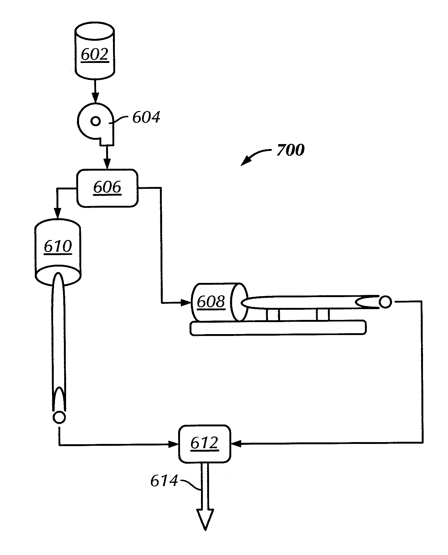
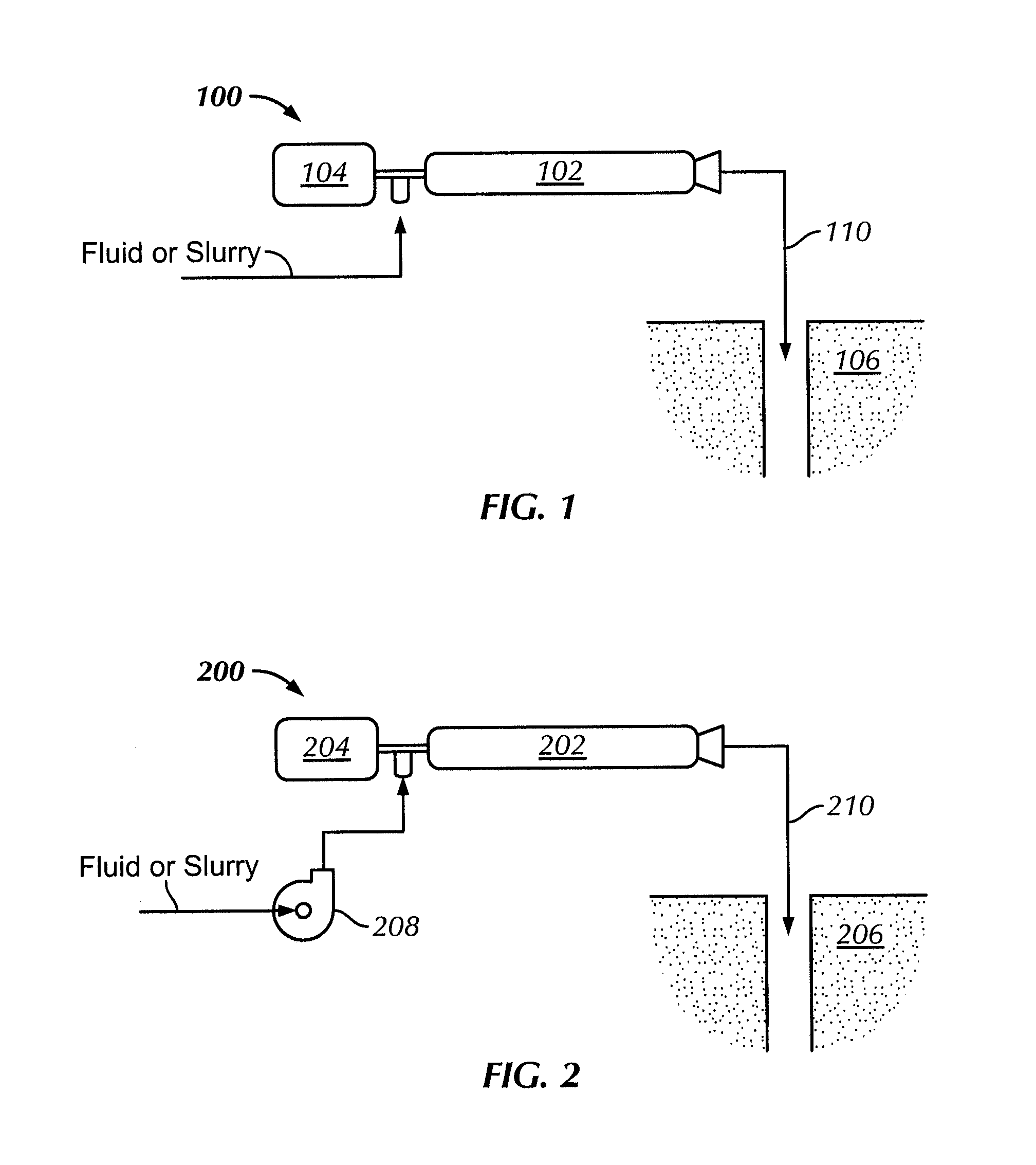
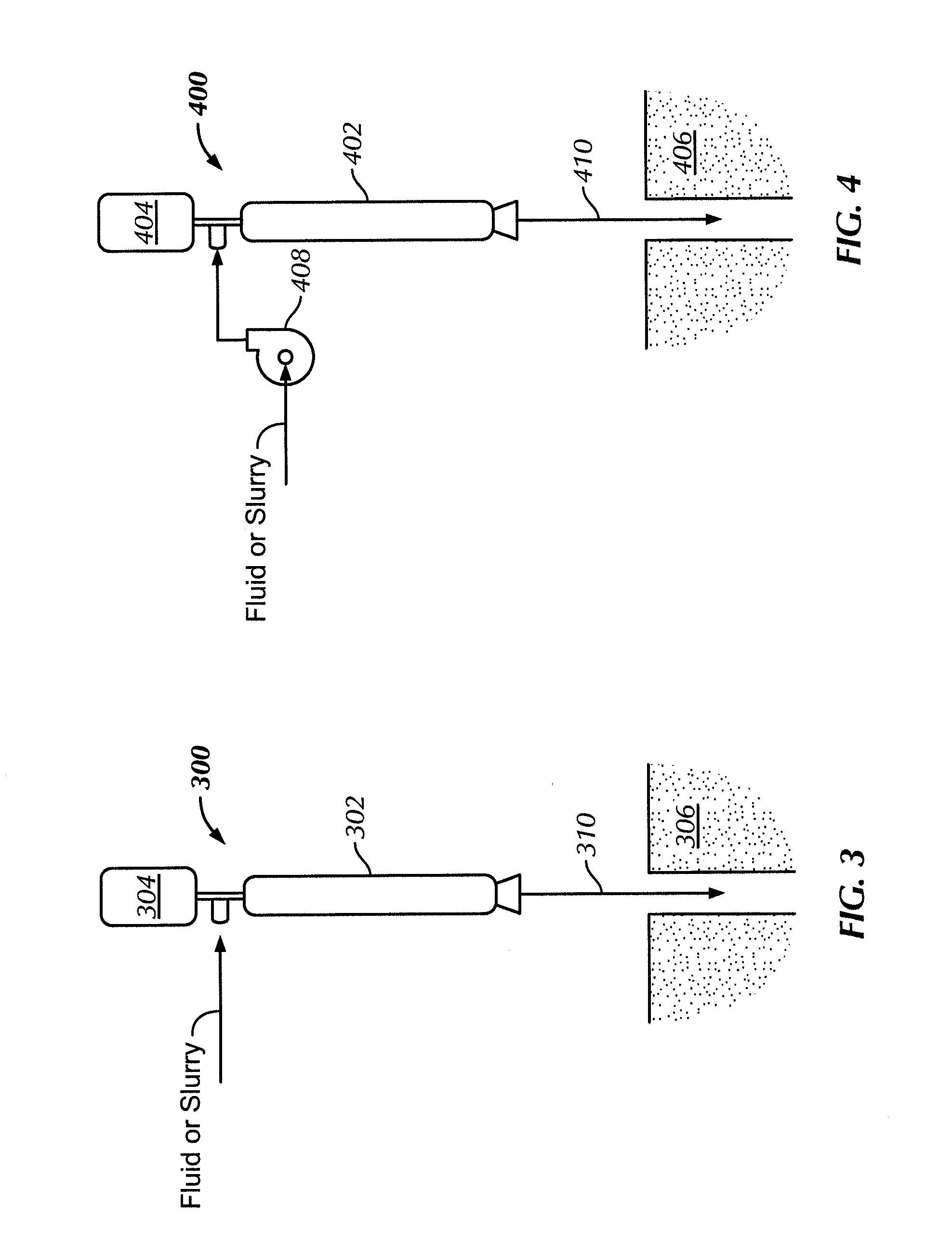
[0024]In one aspect, embodiments disclosed herein generally relate to a method or process of cuttings re-injection. In particular, embodiments disclosed herein relate to methods and systems for injecting a slurry, viscous bio-polymer based fluids, and / or other associated effluents, into a formation. More specifically, embodiments disclosed herein relate to a method and system for cuttings re-injection using a multi-stage centrifugal pump.

[0025]During cuttings re-injection operations, a slurry is prepared including a fluid and cleaned drill cuttings. Solid waste, e.g., drill cuttings, is typically degraded, or reduced, to a size of less than 300 microns. The solid waste may be degraded using centrifugal pumps or grinding machines. Typically, the slurry is prepared by mixing together drill cuttings, previously classified by size, to a desired ratio with a fluid, such that a slurry is created that contains a desirable percentage of drill cuttings to total volume. Those of ordinary skil...


PUM


Abstract

A system for injecting a fluid into a formation including a fluid, and at least one injection pump configured to receive the fluid, the at least one pump including a centrifugal pump having at least two stages configured to increase the pressure of the received fluid is disclosed. The system further includes a drive device coupled to the injection pump. A method of injecting a fluid downhole including providing a fluid to an injection pump, the injection pump including a centrifugal pump having at least two stages, pumping the fluid through the at least two stages of the centrifugal pump, thereby increasing the pressure of the fluid, and injecting the fluid from the injection pump into a wellbore is also disclosed.

Description

[0001]This application is a continuation in part of prior PCT / US2008 / 075814, filed Sep. 10, 2008, which claims priority to U.S. Provisional Application No. 60 / 972,117, filed Sep. 13, 2007, the disclosures of which are hereby incorporated by reference.BACKGROUND OF INVENTION[0002]1. Field of the Invention[0003]Embodiments disclosed herein generally relate to a method and system for fluid injection. In particular, embodiments disclosed herein relate to a method and system for injecting viscous fluids, unweighted fluids, low-weighted fluids, and / or slurries in a downhole formation.[0004]2. Background Art[0005]In the drilling of wells, a drill bit is used to dig many thousands of feet into the earth's crust. Oil rigs typically employ a derrick that extends above the well drilling platform. The derrick supports joint after joint of drill pipe connected end-to-end during the drilling operation. As the drill bit is pushed further into the earth, additional pipe joints are added to the ever...

Claims


Application Information

Patent Timeline
Patent Type & Authority Patents(United States)
IPC IPC(8): E21B43/16
CPCE21B41/0057
Inventor SHERWOOD, JOEMCEWEN, GREGWOOLSEY, GARYNEWMAN, KATERINA
Owner MI
Learn More