
Low-melting-point metal multi-dimensional structure liquid phase printing system and method

A low-melting-point metal and printing system technology, applied in the liquid phase printing method of multi-dimensional structure and its system field, can solve the problems of long solidification and forming time of structural parts, difficult printing process control, weak air cooling effect, etc., and achieve lifting speed and The scope of application, the temperature and flow field speed are convenient to adjust, and the effect of a wide range of sustainable development

Active Publication Date: 2015-03-18
TECHNICAL INST OF PHYSICS & CHEMISTRY - CHINESE ACAD OF SCI
View PDF6 Cites 42 Cited by
  • Summary
  • Abstract
  • Description
  • Claims
  • Application Information

AI Technical Summary

Problems solved by technology

[0003] So far, the existing 3D printing technology can only produce non-functional structural supports due to the use of materials such as plastics or polymers. The method still faces great difficulties in the simultaneous production of mechanical and electronic components. The existing methods generally have shortcomings such as long production time and limited applicable objects.
In particular, when making conductive metal components, due to the high melting point of conventional metal materials such as copper and aluminum, high sintering temperatures are often required, which consumes a lot of energy, and the conventional air cooling effect is weak, and the structural parts are solidified and formed. The time is too long, the control of the printing process is difficult, and improvement is urgently needed

Method used


Image

  • Low-melting-point metal multi-dimensional structure liquid phase printing system and method
  • Low-melting-point metal multi-dimensional structure liquid phase printing system and method
  • Low-melting-point metal multi-dimensional structure liquid phase printing system and method

Examples


Embodiment 1

[0040] Example 1: Printing method of 0-dimensional metal structure

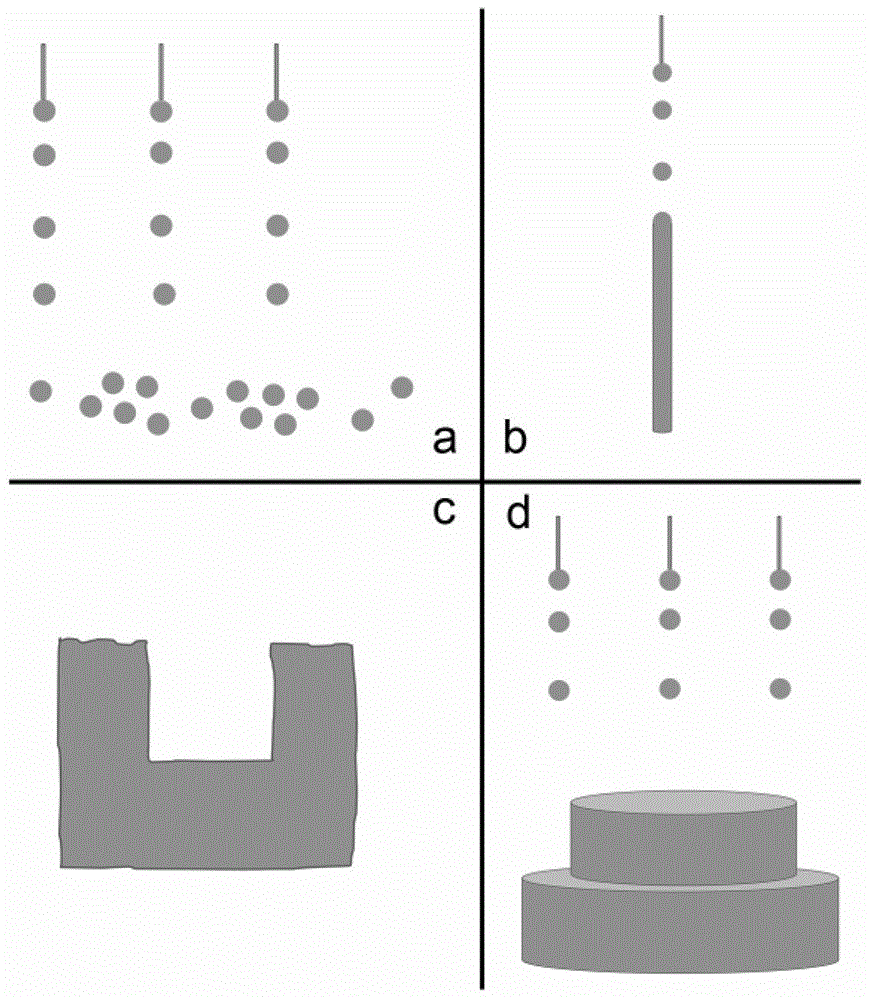
[0041] printing system such as figure 1. , including: a syringe pump array 1, an injection needle array 2, a liquid metal pool 3, a constant temperature box 4, a constant temperature bath 5 and a computer 6; the syringe pump array includes 2×2 syringe pumps arranged in a 2×2 array, and each syringe pump The inlet is connected to the liquid metal pool; the injection needle array includes 2×2 injection needles arranged in a 2×2 array, the injection needles are vertically opposite to the liquid surface of the constant temperature bath, and the liquid inlet of the injection needle is connected to the outlet end of the injection pump one by one connect. The syringe pump array 1, the injection needle array 2, the liquid metal pool 3, and the constant temperature bath 5 are all arranged in a constant temperature box; the computer is connected with the syringe pump array. In this embodiment, the needle is selected...

Embodiment 2

[0047] Embodiment 2: The multi-dimensional printing method of 1-dimensional metal structure

[0048] The system is as in Example 1.

[0049] The 1D metal structure to be printed is a metal wire, and Bi is selected 31.6 In 48.8 sn 19.6 The alloy (melting point is 59°C) is the printing ink. The constant temperature box 4 is set at 80° C., the constant temperature water bath 5 is set at 45° C., and contains water. The syringe pump array includes 2×10 syringe pumps, arranged in a 2×10 array, and the inlet of each syringe pump is connected to the liquid metal pool; the injection needle array includes 2×10 injection needles, arranged in a 2×10 array, and the injection needles are connected to the constant temperature The liquid surface of the bath is vertically opposite, and the liquid inlet of the injection needle is connected with the outlet of the injection pump one by one. According to the diameter of the metal wire to be printed, the injection speed of the corresponding ne...

Embodiment 3

[0051] Embodiment 3 Multi-dimensional structure printing method of 2-dimensional metal structure

[0052] The system is as in Example 1.

[0053] The 2D metal structure to be printed is a "concave" metal surface, and Bi is selected 31.6 In 48.8 sn 19.6 The alloy (melting point is 59°C) is the stock solution. The constant temperature box 4 is set at 80° C., the constant temperature bath 5 is set at 45° C., and contains water. The syringe pump array includes 80×80 syringe pumps, arranged in a 2×2 array, and the inlet of each syringe pump is connected to the liquid metal pool; the injection needle array includes 80×80 injection needles, arranged in an 80×80 array, and the injection needles are connected to the constant temperature The liquid surface of the bath is vertically opposite, and the liquid inlet of the injection needle is connected with the outlet of the injection pump one by one.

[0054] Firstly, the structure to be printed is designed and the printing program is...


PUM

PropertyMeasurementUnit
The inside diameter ofaaaaaaaaaa
Melting pointaaaaaaaaaa
Diameteraaaaaaaaaa

Abstract

The invention provides a low-melting-point metal multi-dimensional structure liquid phase printing system. The low-melting-point metal multi-dimensional structure liquid phase printing system comprises an injection pump array, an injection needle array, a liquid metal tank, a thermostat, a thermostatic bath and a control unit. The injection pump array includes m*n of injection pumps and an inlet of every injection pump is connection with the liquid metal tank. Injection needles are perpendicular to the thermostatic bath and liquid inlets of the injection needles are connected to outlet ends of the injection pumps respectively. The control unit is connected to the injection pump array. A low-melting-point metal multi-dimensional structure liquid phase printing method uses the smart control mechanism of fluid for applying effective buffer, crushing and buoyancy actions to liquid metal injection droplets, and the liquid cooling treatment more efficient than a traditional gas cooling mode can be provided for enabling liquid metal injected into a liquid phase environment to be quickly solidified due to the large heat capacity, so that short-time forming of a multi-dimensional structure is achieved, and meanwhile the oxidation not easy to avoid in a traditional method is reduced.

Description

technical field [0001] The invention belongs to the field of printing, and in particular relates to a multi-dimensional structure liquid phase printing method and a system thereof. Background technique [0002] 3D printing technology is a kind of rapid prototyping method and a form of realization of additive manufacturing. It has developed particularly rapidly in the past one or two years. The conventional 3D printing method is to use the computer to pre-design the 3D model of the product, segment and discretize the model through software, decompose the printing process, and then use laser beams, hot-melt nozzles, etc. to process metal, plastic, ceramics and other materials Carry out layer-by-layer stacking and bonding, and finally superpose and form, so as to manufacture the designed end product. So far, most of this kind of processing is done in the air, with the help of gas cooling to naturally form structural parts, or to cool high-temperature liquid structures through ...

Claims


Application Information

Patent Timeline
IPC IPC(8): B22F3/115
Inventor 王磊刘静
Owner TECHNICAL INST OF PHYSICS & CHEMISTRY - CHINESE ACAD OF SCI
Learn More