
Low smoke, fire and water resistant cable coating

a fire-resistant, low-smoke technology, applied in the direction of anti-corrosion paints, rubber insulators, textiles and paper, etc., can solve the problems of gas evolution (i.e. hydrogen chloride), affecting the performance of wet electrical devices, and affecting the safety of workers, etc., to achieve the effect of improving wet electrical performance and limited smoke characteristics

Active Publication Date: 2014-04-22
GENERAL CABLE TECH CORP
View PDF47 Cites 16 Cited by
  • Summary
  • Abstract
  • Description
  • Claims
  • Application Information

AI Technical Summary

Benefits of technology

The present invention introduces a new and improved cable coating that combines multiple functions in one layer, including low-smoke emission, fire-resistance, and moisture resistance. The coating exhibits good electrical performance, meets the requirements of a small gauge fire rating, and minimizes smoke production during a cable tray usage test.

Problems solved by technology

Wire and cable insulation or coating compositions are normally quite flammable.
As a result, they can pose a fire hazard in power plants, distribution areas, manholes, and buildings.
Halogens, however, have a major drawback in that the gases evolved (i.e. hydrogen chloride, hydrogen fluoride and hydrogen bromide) during burning, or even merely overheating, are corrosive as well as being toxic.
As a result, the use of halogenated additives or halogenated compounds are not recommended in enclosed locations.
A drawback of this system is that the hydrated metal oxide is polar which absorbs moisture when the cable is exposed to a wet environment, resulting in a reduction in the electrical insulation properties of the coating composition.
None of the documents discussed above address the problem of moisture resistance in a fire resistant cable insulation.
As has been previously discussed, exposure of a fire resistant cable to a wet environment significantly reduces the dielectric insulation properties of the cable coating, which can be a significant problem for underground cables, cables used on ships, and under water cables.
Although both WO 98 / 40895 and U.S. Pat. No. 5,912,436 address low smoke emission, fire-resistance and moisture resistance in a coating, the coating comprises multiple layers which significantly increases the construction cost and complexity of the cable.

Method used


Image

  • Low smoke, fire and water resistant cable coating
  • Low smoke, fire and water resistant cable coating

Examples


example 1

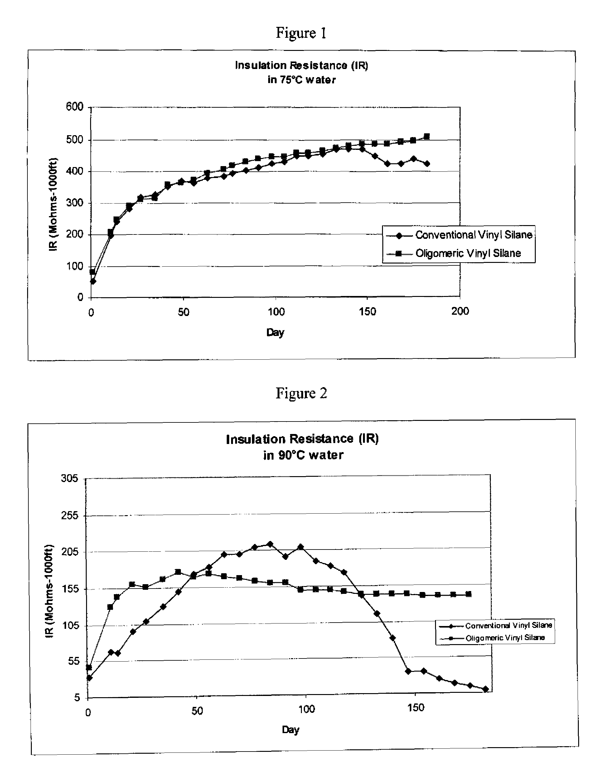
Comparison of Cables Coated With Conventional Silane and Oligomeric Silane Containing Compositions

[0062]Compositions containing either conventional silane or oligomeric silane were made according to the following formulations:

[0063]

Formulas (Relative to FIGS. 1 and 2 and Tables 1 and 2)ConventionalOligomericSilaneSilaneEthylene-octene copolymer (0.879292density, 1 MI)Ethylene vinyl acetate copolymer (9% VA)88Phenolic Antioxidant1.251.25Dibasic lead pthalate dispersion7.57.5Vinyl Silane treated clay2020Vinyl silane treated Mg(OH)2180Struktol WB 22222Polybutadiene Styrene Copolymer33Vinyl Oligomeric silane treated Mg(OH)2180Peroxide1.61.6Total PHR315.4315.4

[0064]The compositions were prepared by a systematic weighment process of each raw material ingredient and charged into an internal Banbury mixer. Each composition was prepared separately through mastication and shear heating to a final batch temperature of approximately 300° F. then discharged and placed onto a 2-roll mill heated t...

example 2

Cables Coated With Vinyl Oligomeric Silane Treated Mg(OH)2 Compositions

[0071]Comparative composition samples 1-11 were made according to the following formulations, with compositions 7-11 containing vinyl oligomeric silane treated Mg(OH)2:

[0072]

Formulas (Relative to Table 3)123456Ethylene-octene copolymer (0.87 density, 1 MI)100100100100100100Phenolic Antioxidant1.51.51.51.51.51.5Dibasic lead pthalate dispersion7.57.57.57.57.57.5Vinyl Silane treated clay202020202020Vinyl silane treated Mg(OH)2180180180180180180Struktol WB 222222222Alkoxysilane-terminated Polybutadiene3Polybutadiene Styrene Copolymer3OH-terminated Polybutadiene3MA-terminated Polybutadiene3Vinyl Oligomeric silane dispersion2Peroxide2.22.22.22.22.22.2Total PHR313.2316.2316.2316.2316.2315.27891011Ethylene-octene copolymer (0.87 density, 1 MI)100100100100100Phenolic Antioxidant1.51.51.51.51.5Dibasic lead pthalate dispersion7.57.57.57.57.5Vinyl Silane treated clay2020202020Struktol WB 22222222Alkoxysilane-terminated Polyb...

example 3

Fire Retardance of Cables Coated with Vinyl Oligomeric Silane Treated Mg(OH)2 Compositions

[0076]Comparative composition samples A-E were made according to the following formulations, with compositions B-D containing vinyl oligomeric silane treated Mg(OH)2:

[0077]

Formulas (relative to fire retardance)ABCDEEthylene-octene copolymer (0.87 density, 1 MI)92909090100Ethylene vinyl acetate copolymer (9% VA)85Ethylene butylacrylate copolymer (17% BA)10105Phenolic Antioxidant1.251.251.251.251.25Dibasic lead pthalate dispersion7.57.57.57.5Vinyl Silane treated clay2020Oligomeric silane treated Boehmite202020Vinyl silane treated Mg(OH)2180180Struktol WB 22222222Polyisoprene-vinyl pyridine copolymer3Polyisoprene-styrene-vinyl pyridine terpolymer33Polybutadiene Styrene Copolymer3Zinc Stannate5552.5Vinyl Oligomeric silane treated Mg(OH)2180180180Zinc Borate2.5Peroxide1.61.61.61.61.6Total PHR317.4320.4320.4312.9315.4

[0078]The comparative compositions were prepared by a systematic weighment process o...


PUM

PropertyMeasurementUnit
densityaaaaaaaaaa
densityaaaaaaaaaa
temperaturesaaaaaaaaaa

Abstract

Cable coatings having effective low-smoke emission, fire resistance and moisture resistance provided by a single layer are described. The cable coatings contain an base polymer, a oxygen containing ethylene copolymer, a fire retardant and a synergistic blend of magnesium hydroxide and aluminum hydroxide. Cables coated with the described coatings have improved wet electrical performance, and satisfactory fire performance and smoke characteristics.

Description

FIELD OF THE INVENTION[0001]The present invention provides a new and improved cable coating. The coating or insulation is effective for low-smoke emission, fire-resistance and moisture resistance and may be used in a single layer.BACKGROUND OF THE INVENTION[0002]Wire and cable insulation or coating compositions are normally quite flammable. As a result, they can pose a fire hazard in power plants, distribution areas, manholes, and buildings. Ignition can easily occur from overheating or arcing. Therefore, flame retardants are generally used in wire and cable coatings to prevent electric sparks and subsequently to prevent the spread of fire along the cable.[0003]Flame retardants such as halogenated additives (compounds based on fluorine, chlorine or bromine) or halogenated polymers, such as chlorosulfonated polyethylene, neoprene, polyvinyl chloride, or the like, are commonly used as flame retardants in wire and cable insulation or coating compositions. Both halogenated additives and...

Claims


Application Information

Patent Timeline
Patent Type & Authority Patents(United States)
IPC IPC(8): D02G3/00H01B3/10
CPCC09D123/22C08L21/00H01B7/295C08L23/0853C08L9/06H01B3/441C08L9/00C08L23/16C08K5/14H01B3/28C08K3/22C08L23/0815C08L23/22C08L2201/02C09D5/18C08K2201/014C09D123/16C08L23/02C08L23/0869C08L15/00C08L23/10C09D121/00C08L11/00C08L23/0892Y10T428/2958Y10T428/2933Y10T428/2927Y10T428/294C08K3/346C08K5/54C08K5/5425C08K9/06C08L25/10C08L2312/00C08L2666/02C08L2666/04
Inventor CLANCY, TIM
Owner GENERAL CABLE TECH CORP
Learn More