
Zirconium oxide and method for the production thereof

a zirconium oxide and zirconium oxide technology, applied in the field of zirconium oxide, can solve the problems of large amount of wastewater obtained in chemical processes, unstabilized phase, and large proportion of undesirable monoclinic, and achieve high electrical conductivity and mechanical strength.

Inactive Publication Date: 2013-02-26
H C STARCK GMBH
View PDF19 Cites 4 Cited by
  • Summary
  • Abstract
  • Description
  • Claims
  • Application Information

AI Technical Summary

Benefits of technology

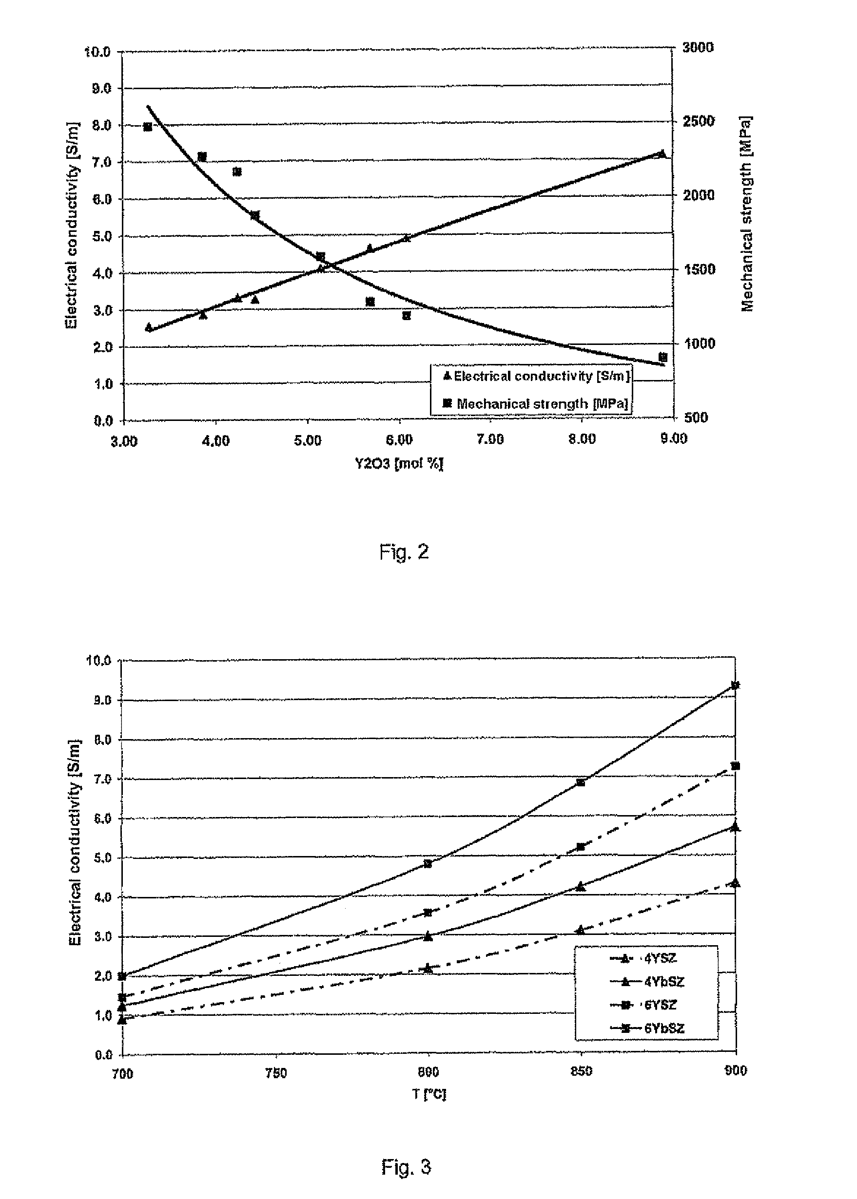
The present invention provides zirconium oxide powders that can be used in ceramic fuel cells. These powders have high electrical conductivities and mechanical strengths after being sintered to gastight bodies. The invention also provides an economical process for producing these zirconium oxide powders. The pulverulent zirconium oxides used in the invention have a fill density of from ≧1.2 to 2.5 g / cm3. This invention allows for the production of highly effective ceramic fuel cells.

Problems solved by technology

Unsatisfactory homogeneity of the stabilizer in the ZrO2 lattice leads to the presence of proportions of undesirable monoclinic, i.e. unstabilized, phases.
The high filtration rate of gel precursors is a decisive disadvantage over the traditional hydroxide precipitation process.
A disadvantage of all wet-chemical processes described is the large amounts of wastewater obtained.
Disadvantages of the process are the high sintering temperatures of >1300° C. and the low homogeneity of the powders, which contain from 25 to 30% by volume of monoclinic phase after sintering.
To minimize the proportions of monoclinic phase, the products are repeatedly milled and heat treated in a plurality of stages, resulting in a significant increase in the product costs.
A disadvantage of the zirconium dioxide powders produced according to the prior art via the mixed oxides process is their unsatisfactory homogeneity of the stabilizers in the crystal lattice.
However, these lead to higher production costs, at least in part due to the additional process steps required (crushing, classification).
Furthermore, the high sintering temperatures lead to undesirably low BFT values and to reduced sinter activity of the powders.
These powders are unsuitable for use in ceramic fuel cells because of their low electrical conductivity and unsatisfactory sinter activity.

Method used


Image

  • Zirconium oxide and method for the production thereof
  • Zirconium oxide and method for the production thereof
  • Zirconium oxide and method for the production thereof

Examples


example 1

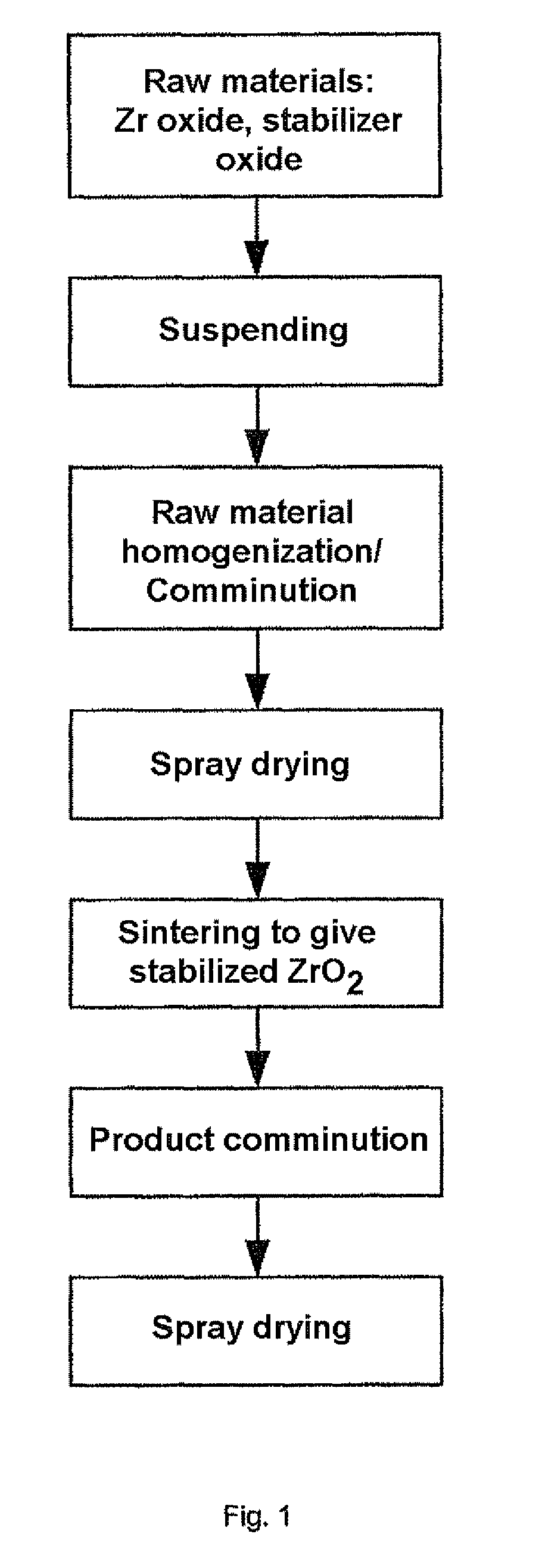
[0087]10.74 liters of deionized water were placed in a water-cooled double-walled reservoir and 23.5 kg of ZrO2 having a specific surface area of 7.54 m2 / g and crystallite edge lengths of a=47 nm, b=58 nm, c=43 nm and 1.56 kg of Y2O3 having a specific surface area of 5.36 m2 / g were suspended by stirring with a high-speed stirrer, i.e. the solids content was 70% by mass. To stabilize the suspension, 0.37 kg of a 1:1 mixture of the two dispersant grades Dolapix CE 64 and Dolapix CA from Zschimmer & Schwarz were firstly added, resulting in an increase in the zeta potential. During milling, further amounts of the Dolapix CA / CE64 dispersant mixture were continuously added in order to continue to achieve sufficient stabilization of the surfaces and charges which had been newly created with progressing comminution, so that the suspension continued to have a low viscosity and could be readily stirred and conveyed during comminution despite a high solids concentration. The suspension was pum...

example 2

[0096]23.5 kg of ZrO2 having a specific surface area of 9.71 m2 / g and crystallite edge lengths of a=36 nm, b=46 nm, c=36 nm and 1.56 kg of Y2O3 having a specific surface area of 5.36 m2 / g were suspended in 10.7 liters of water. The solids content of the suspension was 70% by mass. The homogenized precursor mixture after spray drying displayed a specific surface area of 19.28 m2 / g. The example was carried out by a method analogous to example 1.

[0097]The zirconium oxide powder obtained had a specific surface area of 9.43 m2 / g, a d90 of 0.57 μm and a fill density of 1.84 g / cm3. The Y2O3 content was 3.5 mol %. The proportion of monoclinic phase in the powder was 39% by volume. The powder was uniaxially pressed at a pressure of 100 MPa to give pressed bodies. The pressed bodies were then isostatically pressed at 2000 MPa to densify them further.

[0098]The pressed bodies displayed a green density of 3.49 g / cm3. The density of the pressed bodies after sintering at 1500° C / 1 h was 6.01 g / cm3...

example 3

[0099]66 kg of ZrO2 having a specific surface area of 6.63 m2 / g and crystallite edge lengths of a=50 nm, b=59 mm, c=44 nm and 4.4 kg of Y2O3 having a specific surface area of 3.74 m2 / g were suspended in 47 liters of water. The solids content was 60% by mass. The milling of the precursors was carried out at a specific net milling energy input of 0.50 kWh / kg of solid. The homogenized precursor mixture after spray drying displayed a specific surface area of 14 m2 / g. The further procedure in the example was analogous to example 1.

[0100]The product obtained had a specific surface area of 10.60 m2 / g, a d90 of 0.64 μm and a fill density of 1.72 g / cm3. The Y2O3 content was 3.5 mol %. The proportion of monoclinic phase in the powder was 50% by volume. The powder was uniaxially pressed at a pressure of 100 MPa to give pressed bodies. The test specimens were then isostatically pressed at 2000 MPa to densify them further.

[0101]The pressed bodies displayed a green density of 3.46 g / cm3. The dens...


PUM

PropertyMeasurementUnit
Temperatureaaaaaaaaaa

Abstract

The invention relates to a pulverulent zirconium oxide containing metal oxides from the group consisting of scandium, yttrium, rare earths and mixtures thereof, processes for producing them and their use in fuel cells, in particular for the production of electrolyte substrates for ceramic fuel cells.

Description

CROSS-REFERENCE TO RELATED APPLICATIONSRelated Applications[0001]This application is a national stage application (under 35 U.S.C. §371) of PCT / EP2007 / 057607, filed Jul. 24, 2007, which claims benefit of German application 10 2006 038602.7, filed Aug. 17, 2006 and German application 10 2006 044 824.3, filed Sep. 20, 2006.BACKGROUND OF THE INVENTION[0002]The invention relates to a pulverulent zirconium oxide containing metal oxides from the group consisting of scandium, yttrium, rare earths and mixtures thereof, processes for producing them and their use in fuel cells, in particular for the production of electrolyte substrates for ceramic fuel cells.[0003]Pure zirconium oxide (ZrO2) exists in three modifications. The cubic high-temperature phase is converted at below 2300° C. into metastable tetragonal zirconium oxide, and the transformation from tetragonal into monoclinic ZrO2 is observed between 1200° C. and 950° C. Transformations between the monoclinic phase and the high-temperat...

Claims


Application Information

Patent Timeline
IPC IPC(8): C01G25/02
CPCC01G25/00B82Y30/00H01M8/1253C04B35/486C04B35/6261C04B35/6262C04B35/6263C04B35/62655C01G25/02C01P2002/52C01P2006/10C01P2006/40H01M2300/0077Y02E60/521Y02E60/525C04B2235/3224C04B2235/3225C04B2235/3244C04B2235/5409C04B2235/5445C04B2235/5454C04B2235/549C04B2235/604C04B2235/608C04B2235/762C04B2235/77C04B2235/96Y02E60/50Y02P70/50C01P2006/12C01F17/218C01F17/224
Inventor LAUBE, JORGGUGEL, ALFREDOTTERSTEDT, RALPH
Owner H C STARCK GMBH
Learn More