Eureka AIR delivers breakthrough ideas for toughest innovation challenges, trusted by R&D personnel around the world.

Liquid-repellent film forming method, inkjet head and inkjet recording apparatus

a liquid-repellent film and film forming technology, applied in the field of liquid-repellent film forming methods, inkjet head and inkjet recording apparatus, can solve the problems of deterioration of image quality, decline of film properties, and lack of sufficient bonding sites (hydroxyl groups: oh groups), so as to prevent the decline of image quality and reduce the amount of liquid. , the effect of high resistan

Active Publication Date: 2013-02-05
FUJIFILM CORP
View PDF5 Cites 4 Cited by
  • Summary
  • Abstract
  • Description
  • Claims
  • Application Information

AI Technical Summary

Benefits of technology

[0013]The present invention has been contrived in view of these circumstances, an object thereof being to provide a liquid-repellent film forming method, an inkjet head and an inkjet recording apparatus, whereby it is possible to form, on the surface of a nozzle plate, a liquid-repellent film having high resistance to various types of liquids, for example, liquids containing alkaline, acidic and neutral water-soluble components, as well as preventing the erasure of the liquid-repellent film even if droplets of alkaline liquid, for example, are ejected though nozzle apertures formed in the nozzle plate, and hence the liquid droplet ejection stability, and the maintenance properties of the nozzle plate can be improved dramatically.

Problems solved by technology

If the ink has adhered to the surface of the nozzle plate (and in particular, to the periphery of the nozzle apertures), ink droplets subsequently ejected from the nozzles are affected and ejection instabilities occur, for instance, variations arise in the ejection direction of the ink droplets, giving rise to a deterioration in image quality.
However, even if the material properties of the liquid-repellent film are improved as in Japanese Patent Application Publication No. 2003-286478, there is a drawback in that if the processing of the underlying layer is incomplete, then sufficient bonding sites (hydroxyl groups: OH groups) are not created.
Then, the bonding between the liquid-repellent film and the underlying layer is not sufficient, and the film properties are declined.
Moreover, even if cleaning and surface activation is carried out by plasma treatment of the underlying layer only as in Japanese Patent Application Publication No. 2009-029068, there is a drawback in that sufficient reaction sites are not created on the surface and a high-density liquid-repellent film having sufficient resistance to alkalis is not obtained.
Over and above the aforementioned drawbacks, a problem that is common to the technologies in Japanese Patent Application Publication Nos. 2003-286478 and 2009-029068 is the fact that the liquid-repellent film is bonded to the nozzle plate through siloxane bonds, which are liable to be hydrolyzed in liquids containing OH groups, such as water or aqueous solutions containing alkalis.
Consequently, if alkaline ink droplets, for example, are ejected through the nozzle apertures of the nozzle plate, as in the inkjet head, then the liquid-repellent film in the related art is liable to be erased by contact with the ink, and it is thus not possible to improve resistance to alkalis.
Furthermore, there is also technology which improves film density by increasing the film thickness, and increases the overall lifespan of the film, even if deterioration occurs, as in the plasma polymerization film in Japanese Patent Application Publication No. 2008-105231; however, this leads to increase in raw material quantity and costs, and moreover, since the film is essentially based on siloxane network, then it is also not possible to improve resistance to alkalis.

Method used


Image

  • Liquid-repellent film forming method, inkjet head and inkjet recording apparatus
  • Liquid-repellent film forming method, inkjet head and inkjet recording apparatus
  • Liquid-repellent film forming method, inkjet head and inkjet recording apparatus

Examples


examples

Practical Example A

[0106]In Practical Example A hereby described, a liquid-repellent film was actually formed on a surface of a nozzle plate by means of the liquid-repellent film forming method according to the present invention, but the present invention is not limited to this example.

[0107]A pressure-resistant glovebox with hermetic sealing capability was prepared and the required experimental equipment was placed therein, whereupon the interior of the glovebox was filled with nitrogen. The experimenters carried out all of the following experiments using the rubber gloves of the glovebox.

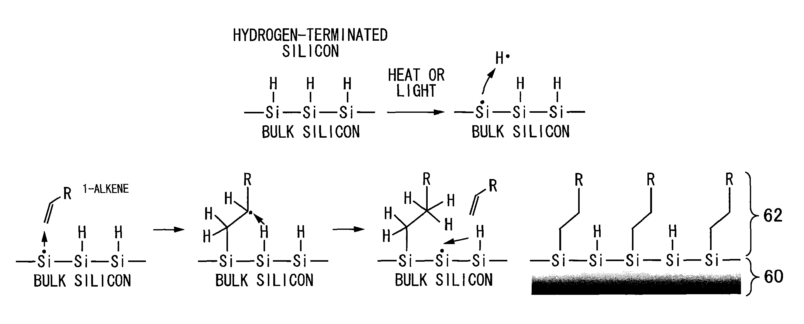
[0108]Firstly, a solution of the raw material (1-hexadecene) of the liquid-repellent film was prepared, whereupon the solution was bubbled with impurity-free nitrogen gas to remove the dissolved oxygen in the solution.

[0109]On the other hand, a nozzle plate (with a natural oxide film thereon) which had undergone cleaning in a cleaning step was subjected to a hydrogen termination process by immersi...

example b

Practical Example B

[0113]In Practical Example B, the surface stability (oxidization rate, carbon contamination, etc.) of a nozzle plate on which a liquid-repellent film had been formed by the heating method in Practical Example A was tested.

[0114]The test involved leaving the nozzle plate of Practical Example on which the liquid-repellent film had been formed in accordance with Practical Example A, at room temperature and atmospheric pressure for 350 hours. Alongside this, a nozzle plate of Comparative Example 1 which had only been subjected to a hydrogen termination process using hydrofluoric acid (an aqueous HF solution) was also left at room temperature and atmospheric pressure for 350 hours. The static angle of contact of pure water was measured over time, on the surface of the nozzle plate of Practical Example on which the liquid-repellent film had been formed, and on the surface of the nozzle plate of Comparative Example 1 which had undergone hydrogen termination.

[0115]FIG. 6 ...

example c

Practical Example C

[0116]In Practical Example C, the alkali resistance was compared, as one example of liquid resistance, between a nozzle plate of Practical Example on which the liquid-repellent film based on silicon-carbon bonds had been formed in accordance with Practical Example A, and a nozzle plate of Comparative Example 2 having a liquid-repellent film based on siloxane bonds (Si—O).

[0117]In order to strengthen siloxane bonds, the liquid-repellent film of Comparative Example 2 was formed by firstly forming a SiO2 film as an underlying film by CVD on the surface of the nozzle plate, as in Japanese Patent Application Publication No. 2009-029068 described above. Then, a fluorocarbon liquid-repellent film material containing chlorosilane as a reactive group was caused to react with the underlying film also by a CVD method, to form a liquid-repellent film bonded to the nozzle plate through siloxane bonds.

[0118]Two samples, the nozzle plate of Practical Example and the nozzle plate...


PUM


Abstract

The method forms a liquid-repellent film on a surface of a nozzle plate having nozzle apertures through which droplets of liquid are ejected. The method includes: a termination process step of carrying out a hydrogen termination process or a halogen termination process on a surface of a nozzle plate, at least a portion of the surface of the nozzle plate being made of a material containing silicon; and a liquid-repellent film formation step of forming a liquid-repellent film on the surface of the nozzle plate after the termination process step by bringing a liquid-repellent film raw material into contact with the surface of the nozzle plate while applying energy to the surface. Each molecule constituting the liquid-repellent film raw material has an unsaturated carbon bond at an end and has a liquid-repellent functional group. The liquid-repellent film is bonded to the surface of the nozzle plate through silicon-carbon bonds.

Description

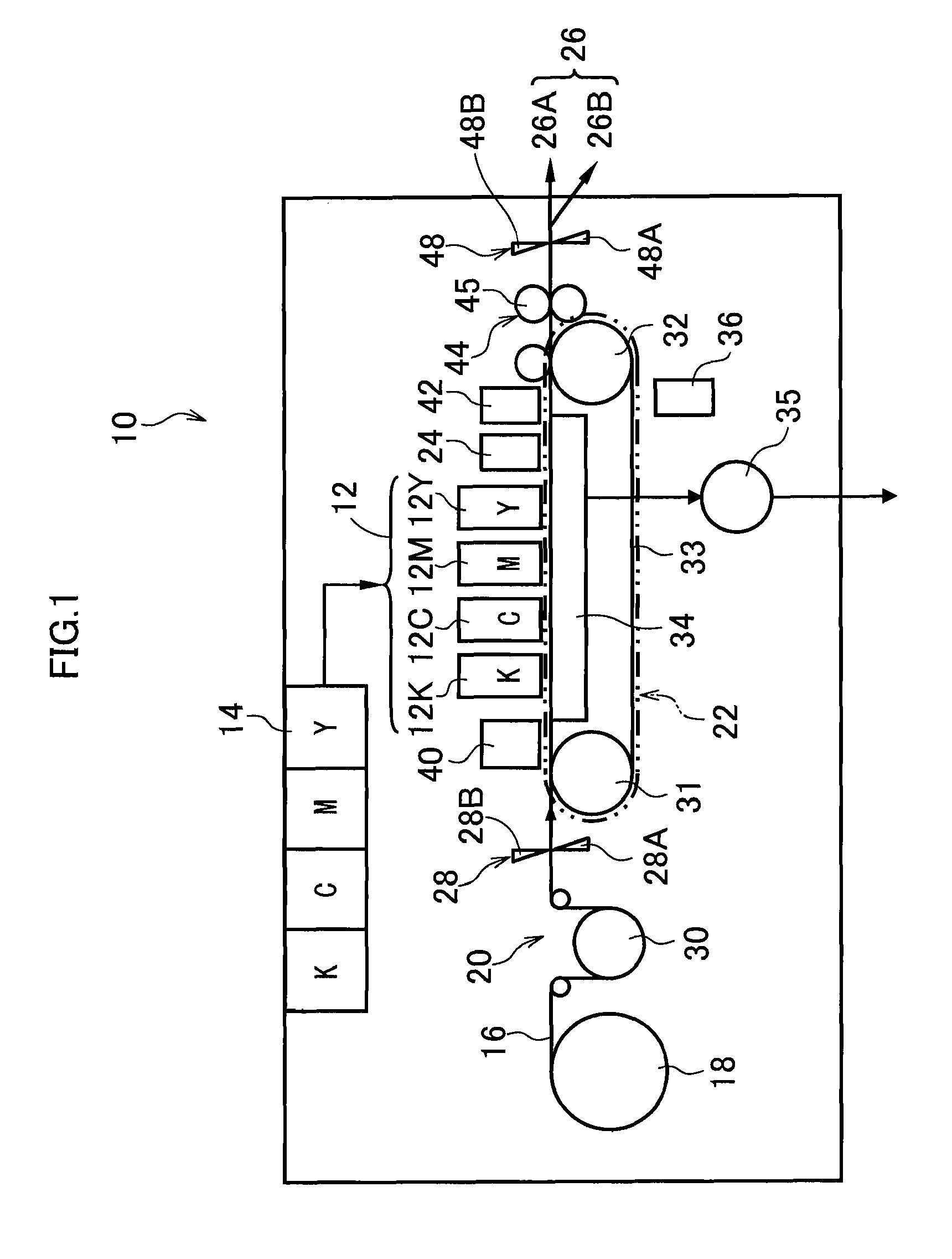
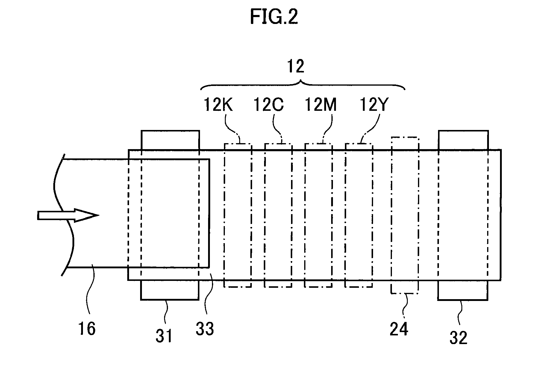
BACKGROUND OF THE INVENTION[0001]1. Field of the Invention[0002]The present invention relates to a liquid-repellent film forming method, an inkjet head and an inkjet recording apparatus, and more particularly, to technology for forming a liquid-repellent film having liquid-repellent properties on a surface of a nozzle plate having nozzle apertures for ejecting liquid droplets.[0003]2. Description of the Related Art[0004]In a recording head (also referred to as an inkjet head) used in an inkjet recording apparatus, droplets of ink are ejected through nozzles having nozzle apertures in the surface of a nozzle plate, which constitutes an ink ejection surface of the recording head. If the ink has adhered to the surface of the nozzle plate (and in particular, to the periphery of the nozzle apertures), ink droplets subsequently ejected from the nozzles are affected and ejection instabilities occur, for instance, variations arise in the ejection direction of the ink droplets, giving rise t...

Claims


Application Information

Patent Timeline
Patent Type & Authority Patents(United States)
IPC IPC(8): B05D1/18
CPCB41J2/14233B41J2/155B41J2/1606B41J2/1642B41J2002/14459B41J2202/20
Inventor UCHIYAMA, HIROKI
Owner FUJIFILM CORP
Why Eureka
Eureka Blog
Learn More