Laser machining method and laser machining apparatus
a laser machining and laser machining technology, applied in metal-working equipment, welding equipment, manufacturing tools, etc., can solve the problems of difficult to improve both machining quality and machining efficiency, take a long machining time when cyclic machining, etc., to achieve the effect of reducing the increase of reducing the input temperature, and reducing the increase of the temperature at the machining hol
- Summary
- Abstract
- Description
- Claims
- Application Information
AI Technical Summary
Benefits of technology
Problems solved by technology
Method used
Image
Examples
first embodiment
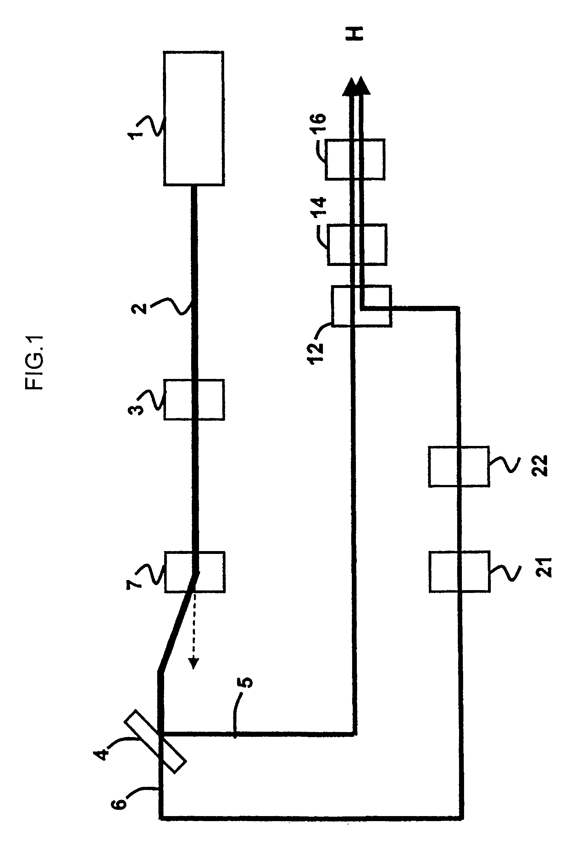
[0043]FIG. 1 is a diagram showing a configuration of an optical system of a first laser machining apparatus suitably applied to the present invention.
[0044]A laser oscillator 1 outputs a P-polarized UV laser beam having frequency F (here 30 KHz). A pulse beam 2 outputted out of the laser oscillator 1 passes through a beam-diameter adjuster 3 that adjusts an outer diameter of the beam and an acousto-optic pulse modulator (AOM, also called an acousto-optic element) 7 that controls pulse energy and then enters a beam splitter 4. It is noted that the AOM 7 can also control the direction of the pulse beam 2 whether it is transmitted in an incident direction as it is (indicated by a dotted line in the figure) or it is lead to an optical path switched from the incident direction.
[0045]The beam splitter 4 reflects 50% of the pulse beam 2 as a split beam 5 and transmits the remainder as a split beam 6. The split beam 5 enters an XY galvanic unit 12 of a head H and the split beam 6 enters a p...
second embodiment
[0071]FIG. 9 is a diagram showing a configuration of an optical system of a second laser machining apparatus that can be suitably applied to the present invention. The same components or those having the same function as those in FIG. 1 are denoted by the same reference numerals and an overlapped explanation thereof will be omitted here.
[0072]The P wave primary beam 2 outputted out of the laser oscillator 1 with oscillating frequency F passes through the beam-diameter adjuster 3 that adjusts an outer diameter thereof and is then reflected by a mirror 20. It is then split into two split beams 8 and 9 having frequency F / 2 and different optical axes by an acousto-optic pulse modulator (AOM) 7. It is noted that the AOM7 not only splits the primary beam into two split beams 8 and 9 but is also capable of controlling one pulse, i.e., pulse energy of the split beams 8 and 9.
[0073]The first split beam 8 enters the XY galvanic unit 12 of a head H. Still more, the second split beam 9 becomes ...
third embodiment
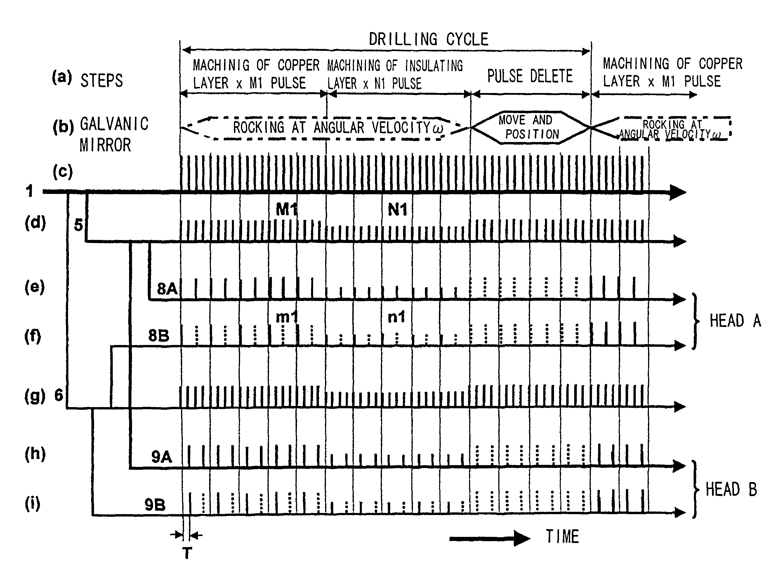
[0081]FIG. 10 is a diagram showing a configuration of an optical system of a third laser machining apparatus that can be suitably applied to the present invention. The same components or those having the same functions with those in FIGS. 1 and 9 are denoted by the same reference numerals and an overlapped explanation thereof will be omitted here. It is noted that when there exist two components having the same function, they are differentiated by denoting subscripts A and B after their reference numerals. FIG. 11 is a chart showing one exemplary irradiation timing in carrying out trepanning by applying the invention, wherein (a) shows machining steps, (b) shows operations of the optical mirrors and (c) shows laser beams outputted out of the laser oscillator. Solid lines in (d) through (i) indicate intensity of each split beam irradiated to the machining hole and irradiation timing thereof, dotted lines therein indicate cases when no beam is irradiated to the machining hole and an a...
PUM
| Property | Measurement | Unit |
|---|---|---|
| diameter | aaaaa | aaaaa |
| thickness | aaaaa | aaaaa |
| thickness | aaaaa | aaaaa |
Abstract
Description
Claims
Application Information
 - R&D
- Intellectual Property
- Life Sciences
- Materials
- Tech Scout
- Unparalleled Data Quality
- Higher Quality Content
- 60% Fewer Hallucinations
Browse by: Latest US Patents, China's latest patents, Technical Efficacy Thesaurus, Application Domain, Technology Topic, Popular Technical Reports.
© 2025 PatSnap. All rights reserved.Legal|Privacy policy|Modern Slavery Act Transparency Statement|Sitemap|About US| Contact US: help@patsnap.com


