
Modular absorption heat sink devices for passive cooling of servers and other electronics

a technology of passive cooling and heat sink, applied in the direction lighting and heating apparatus, instruments, etc., can solve problems such as wear and damage of mechanical pumps or compressors, and achieve the effects of improving overall efficiency of servers, convenient manufacturing of heat sinks, and efficient and flexible design

Active Publication Date: 2012-10-02
ORACLE INT CORP
View PDF4 Cites 3 Cited by
  • Summary
  • Abstract
  • Description
  • Claims
  • Application Information

AI Technical Summary

Benefits of technology

[0011]The use of absorption heat sink devices to cool electronic components provides a number of advantages in the areas of thermal management and design, in manufacturing, in reliability, and in cost. Regarding thermal management and design, it is believed that incorporating the absorption refrigeration technology in the form of a passive heat sink device represents one of the widest ranges of thermal management schemes recently developed in the electronics industry for flexible, passive cooling of electronics components (such as components in a data center that may be generating differing amounts of heat and can be served by different capacity heat sink devices). The differing sized or capacity heat sinks are ideally suited for integration with selective provisioning tools such as CSTH or other telemetry products provided in a computer system to provide intelligent provisioning of workload to differing heat flux components that are cooled by appropriate heat sinks (e.g., that have refrigeration cycles effectively actuated with the waste heat of the matched processor or electronics component), which is particularly useful for achieving improved overall efficiency in servers and other computing devices with dynamically varying workload demands. With regard to manufacturing, as opposed to applications of active cooling system, utilizing absorption refrigeration cooling in the body or shell of a heat sink device provides an efficient and flexible design that facilitates manufacturing of the heat sinks and also the manufacture of high heat flux components, such as high-performance processors for servers and other applications, that can be cooled with the heat sink devices. With regard to reliability, the absorption heat sinks are effective in minimizing the hot regions inside of a server box or other electronics product, and this increases the reliability of the electronic components in use or in the field. Passive, absorption heat sinks integrated with computer server internal components, for example, do not have mechanical pumps or compressors that could possible wear out or break down. With regard to cost, using the passive heat sinks with contained absorption refrigeration cycle systems provides an opportunity for drastically reducing the cost of thermal management such as for servers in data centers and the like. Costs are reduced in part because the cooling system works on the basis of converting waste heat generated by the high-heat and high-power processors and electronic components in the servers into the energy required to activate or provide the needed cooling at the junction between the component and the heat sink (e.g., the heat transmitted from one or more high temperature surfaces of an electronic component is used to heat the absorbent or working absorbing fluid and activate / drive the absorption cooling cycle in the heat sink and no other power is required to maintain the junction temperature within a desired temperature range).

Problems solved by technology

Passive, absorption heat sinks integrated with computer server internal components, for example, do not have mechanical pumps or compressors that could possible wear out or break down.

Method used


Image

  • Modular absorption heat sink devices for passive cooling of servers and other electronics
  • Modular absorption heat sink devices for passive cooling of servers and other electronics
  • Modular absorption heat sink devices for passive cooling of servers and other electronics

Examples


embodiment 400

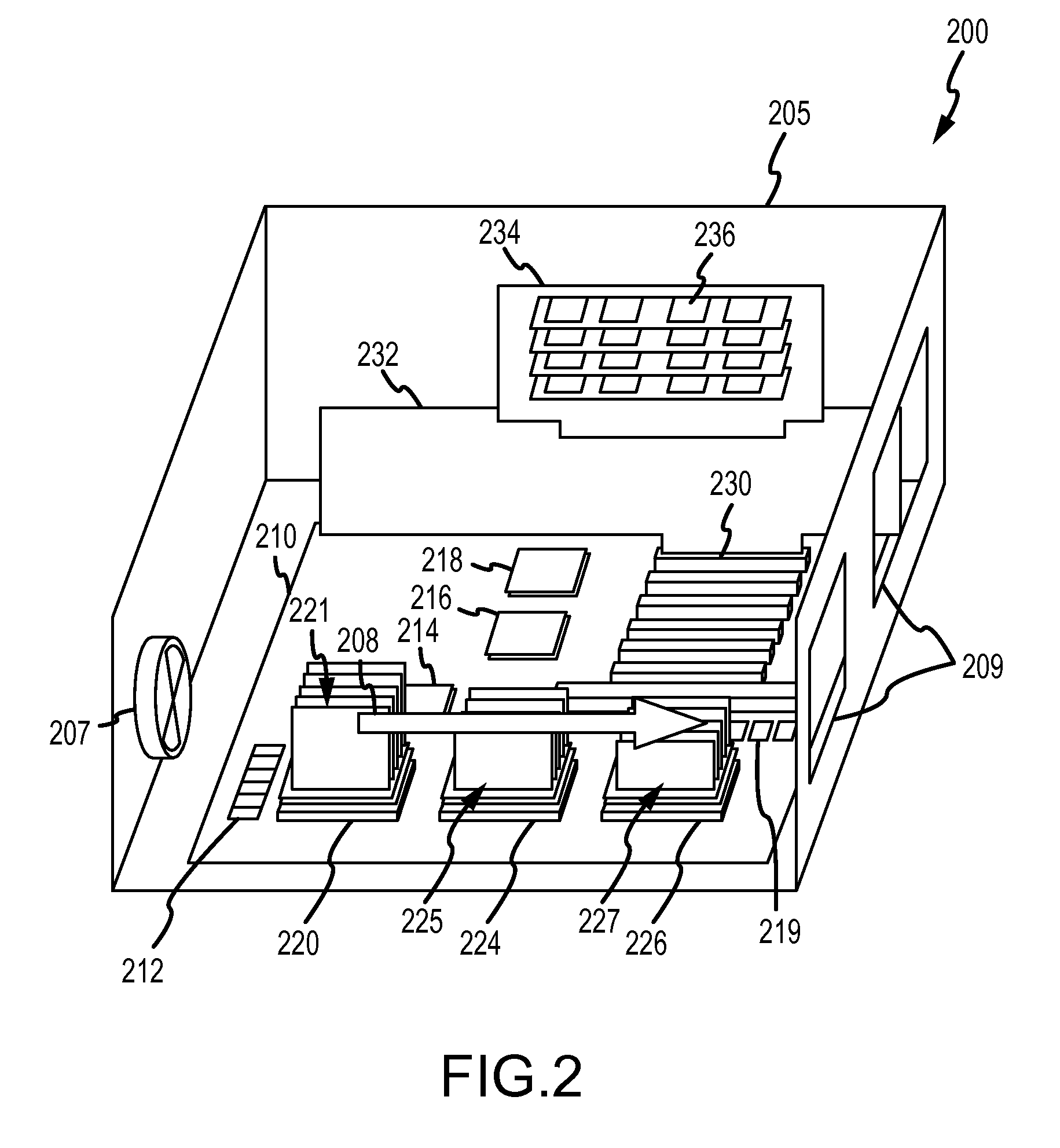
[0032]The heat sink assembly 300 may be mounted in an electronics product (such as a server) 400 shown in FIG. 4. As shown, the electronics product 400 includes a board 410 on which a number of electronic components are mounted. Particularly, the product 400 includes an electronic component 420 mounted on the board 410, and the component 420 may require thermal management to dissipate a particular quantity of heat during its operation. To this end, the heat sink assembly 300 is mounted over the electronic component 420 such that the two devices abut at a heat transfer (or thermal interface) junction 424. Heat transferred from component 420 is used to activate an absorption refrigeration cycle in the assembly 300, and beat is removed from the assembly 300 by cooling air. The cooling air in this embodiment 400 is drawn through the cooling fins 324 of the assembly 300 via a cooling fan 430 that is mounted immediately adjacent (in this exemplary but not limiting embodiment) on the board...

embodiment 530

[0034]According to one aspect of the embodiment 530 shown in FIG. 5, the assembly 530 includes two compartments, i.e., a generator compartment 532 and an absorber compartment 540. The generator compartment 532 is maintained at a lower pressure, P1, that is topically below ambient (or sub-atmospheric), and the compartment 532 may include walls that enclose an internal volume or space in which a volume of a working absorbing fluid 534 is provided. The working absorbing fluid 534 is positioned such that heat transferred from the hot surface 526 of component 520 heats the working absorbing fluid 534 and activates an absorption refrigeration cycle in assembly 530. One or more bubble pumps 538 are provided to transfer working fluid from the generator compartment 532 to the absorber compartment 540 (e.g., a pump that in general raises the working absorbing fluid, that has been heated by the activation or received heat from the electronic component surface 526, by introducing bubbles (e.g.,...

embodiment 630

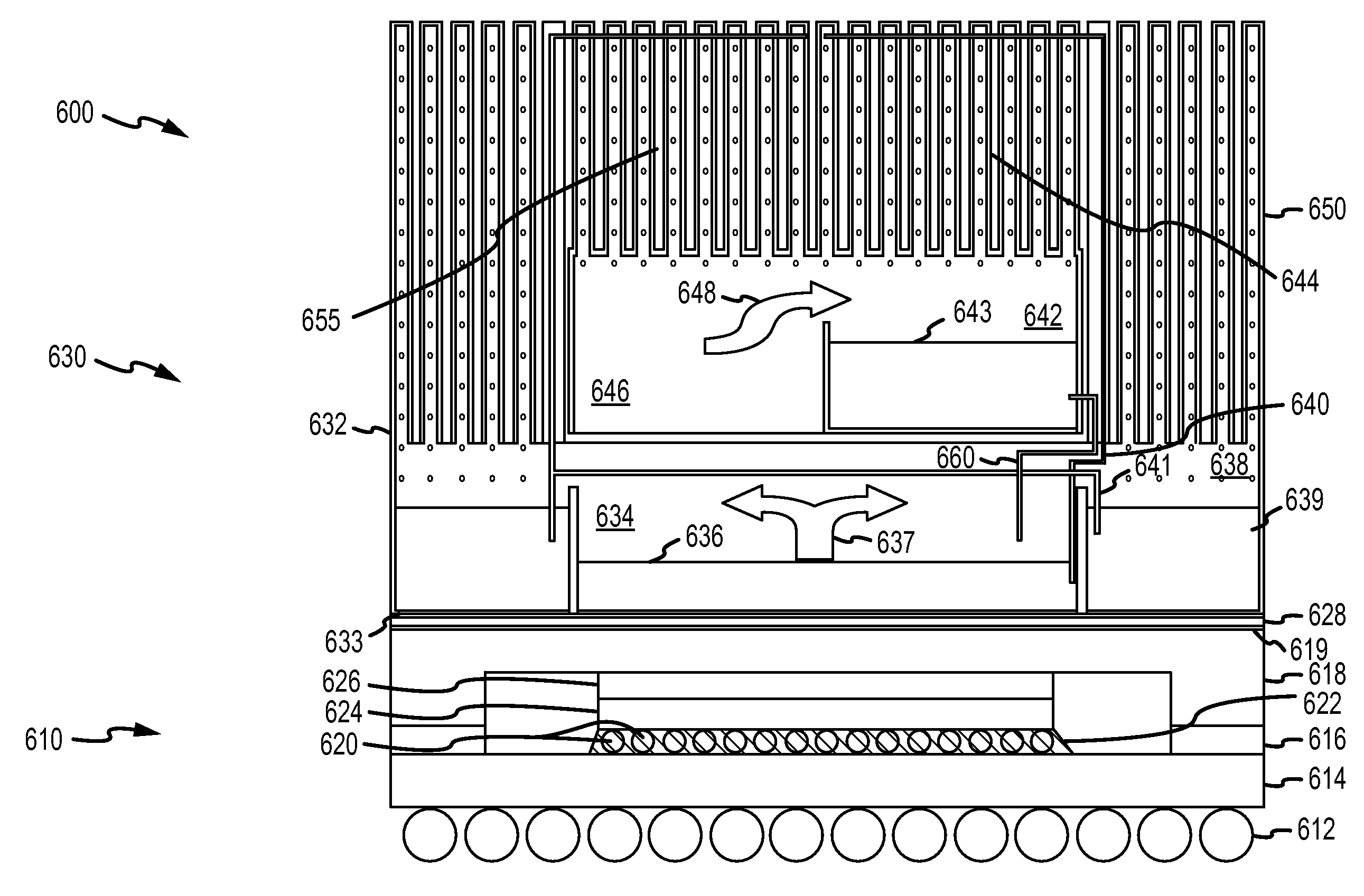
[0037]With this general understanding of an absorption heat sink understood (e.g., a passive cooling device with a pair of compartments at differing pressures connected by a pump(s) and with a heat exchanger for removing received / activation heat), it may be useful to describe a more specific embodiment showing more clearly components and fluid flow used to provide a heat sink of the invention. One exemplary thermal management system 600 is shown in FIG. 6. As shown, an absorption heat sink device 630 is mounted over an electronic component 610. FIG. 6 shows a schematic diagram of a heat-activated, absorption heat sink 630 that is typically miniature as the component 610 has small dimensions (e.g., dimensions associated with a CPU, ASIC, or similar device) and also may be modular and field removable for each installation and removal. Further, as discussed above, the device 630 may be unitary in that components for an absorption refrigeration cycle are provided within a single shell / h...


PUM


Abstract

A passive heat sink for cooling an electronic component such as a high-performance processor. The heat sink includes a shell with a surface that is positionable adjacent a heat generating surface of the electronic component. The shell includes a heat exchanger portion with cooling fins extending outward and positioned in a fan-provided airflow. A generator compartment is provided within the shell with a generator vessel for containing an absorbent, and the generator compartment is maintained at a pressure lower than ambient. The generator compartment conducts heat away from the electronic component to the absorbent in the generator vessel. An absorber compartment, at a pressure lower than the generator compartment, is provided within the shell above the generator compartment, and, in use, an absorption refrigeration cycle contained within the shell is activated by heat from the electronic component. A bubble pump moves absorbent from the generator compartment to the absorber compartment.

Description

BACKGROUND OF THE INVENTION[0001]1. Field of the Invention[0002]The present invention relates, in general, to methods and systems for cooling electronic components such as processors in servers and other computing devices, and, more particularly, to an enhanced heat sink assembly or device that can be attached to a heat generating surface of electronic components such as a processor to provide cooling based on the absorption refrigeration cycle in a passive manner, e.g., without use of compressors and motorized pumps.[0003]2. Relevant Background[0004]Removal of heat has become one of the most important challenges facing computer designers as failure to adequately cool devices can cause failure or operating problems. The rate of power dissipation from electronic components such as from processors (or CPUs) in high-performance server units continues to increase. For example, in servers and disk storage systems, the heat load per product footprint (or Watts / square feet) has grown from ...

Claims


Application Information

Patent Timeline
Patent Type & Authority Patents(United States)
IPC IPC(8): F25B15/00F25B15/16
CPCG06F1/20H01L23/427H01L23/467H01L2924/0002H01L2924/00
Inventor HEYDARI, ALIGROSS, KENNETH C.
Owner ORACLE INT CORP
Learn More