Laser pulse shaping system
a pulse shaping and laser technology, applied in the field of laser systems, can solve the problems of unrealistically high electrical energy consumption, commercial impracticality, and inability to commercially practical femtosecond lasers until recently, and achieve the effects of improving the encoding-decoding functionality of pulses, reducing the cost of operation, and being convenient to set up and us
- Summary
- Abstract
- Description
- Claims
- Application Information
AI Technical Summary
Benefits of technology
Problems solved by technology
Method used
Image
Examples
example 1
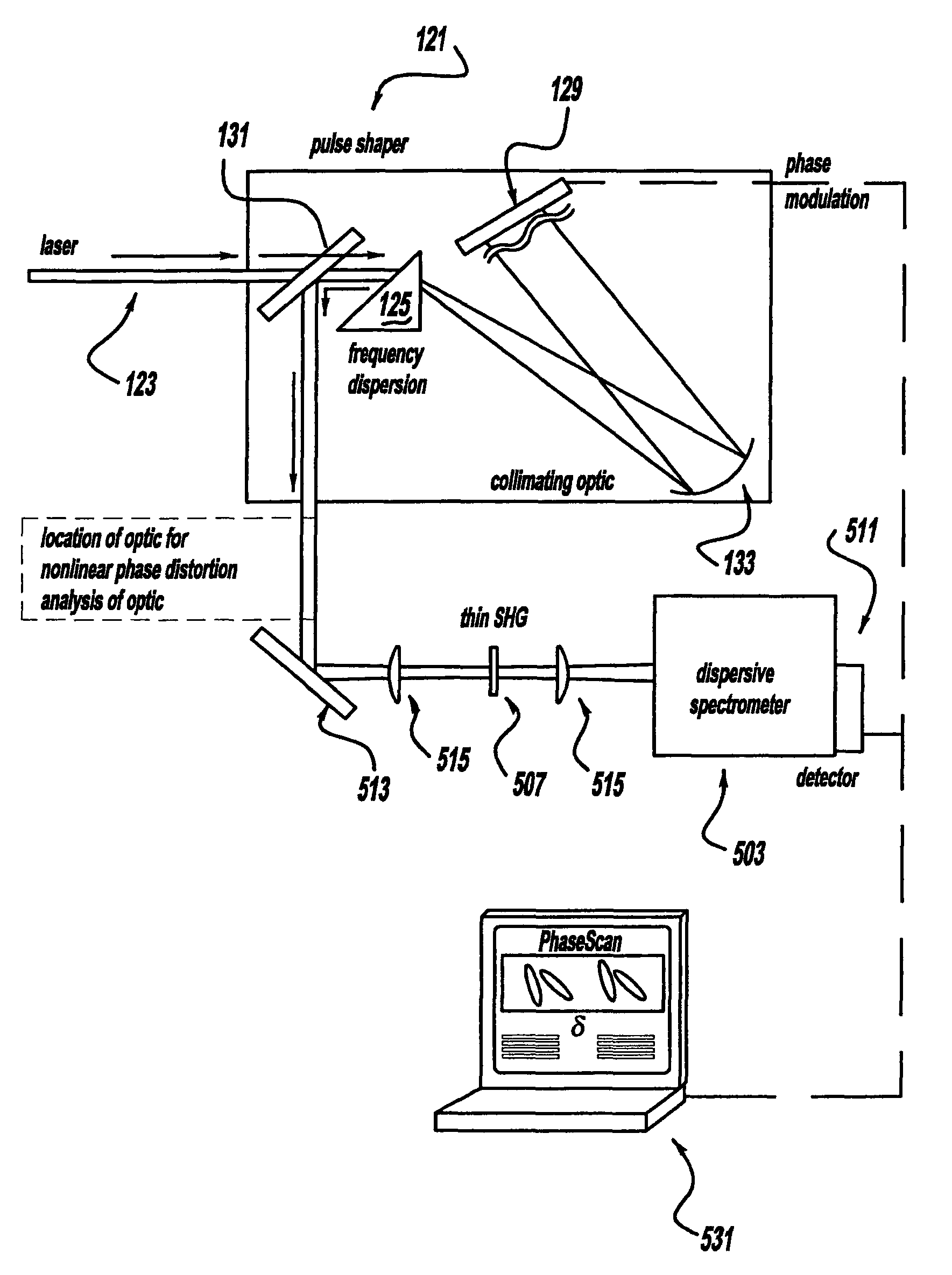
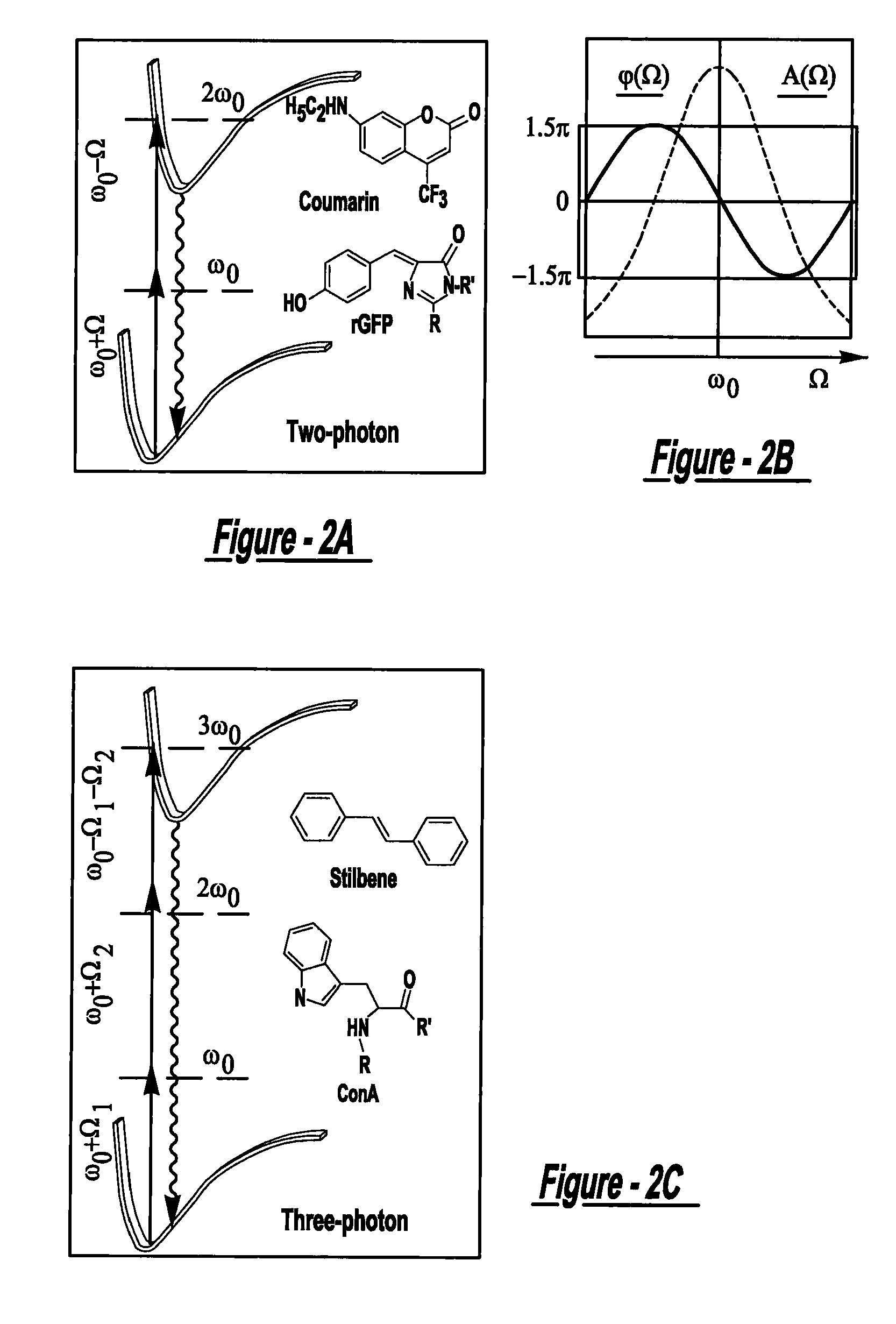
[0048]The experiments in all of the following examples were carried out using an amplified titanium sapphire laser producing 50 fs pulses. The pulses were shaped using a spatial light modulator (hereinafter “SLM”) at the Fourier plane of a zero-dispersion two grating arrangement. The two independent modulator plates, based on liquid crystal technology in the SLM (128 pixels each), were calibrated so that only phase delays were introduced without changes to the output spectrum, intensity, and polarization. The shaped pulses centered at 809 nm were characterized by second harmonic generation frequency resolved optical gating. When all phases were set to zero, laser pulses were near transform limited. Unless indicated otherwise, measurements were made with pulse energies of 0.4 μJ / pulse at the sample. Experiments were carried out by setting the phase function equal to a sinusoid, as shown in FIG. 2B, in the 779-839 nm spectral range. Emission from one photon or multiphoton induced proc...
example 2
[0052]Experimental results for various samples obtained with a full-period sinusoidal phase mask are shown in FIGS. 4A-4G. FIG. 4A shows one photon laser induced fluorescence (hereinafter “1PLIF”) of IR144 observed at 842 nm as a function of phase mask position. This measurement was made with 0.3 nJ / pulse to avoid nonlinear processes at the specimen. It is noteworthy that one photon process in the weak field regime show no dependence on phase shaping. FIG. 4B shows results for the two photon laser induced fluorescence (hereinafter “2PLIF”) from Coumarin collected at 500 nm. The data in FIG. 4C shows the dependence of 2PLIF in recombinant green fluorescent protein (hereinafter “rGFP”) detected at 505 nm. The data in FIG. 4D corresponds to the intensity of the second harmonic generation (hereinafter “SHG”) signal at 405 nm from a 0.3 mm β-barium borate crystal. The maximum and minimum signal for SHG coincides with that observed for 2PLIF but is not identical.
[0053]With reference to FI...
example 3
[0055]FIG. 5A presents the maximum discrimination between linear and nonlinear response observed for intense pulses (0.5 μJ / pulse). Separate detectors simultaneously collected the 1PLIF from IR144 solution and a portion of the continuum output. Maximum and minimum contrast ratios of >103:1 and 1:0.6 were obtained for one photon process versus continuum, respectively, as shown in FIGS. 5A and 5B. This control is extremely valuable when one is interested in linear processes under high-flux conditions, like in laser microscopy or in optical fiber communications. Using the simple phase function discussed earlier, particular windows of opportunity to control second versus higher order processes can be employed as demonstrated in FIGS. 5C and 5D. For certain values of δ, continuum generation even for relatively high intensity laser pulses (˜1 μJ / pulse) can be completely suppressed. FIGS. 5C and 5D show that maximum and minimum contrast ratios of >103:1 and 1:4 were obtained for 2PLIF vers...
PUM
 Abstract
Description
Claims
Application Information
 - R&D
- Intellectual Property
- Life Sciences
- Materials
- Tech Scout
- Unparalleled Data Quality
- Higher Quality Content
- 60% Fewer Hallucinations
Browse by: Latest US Patents, China's latest patents, Technical Efficacy Thesaurus, Application Domain, Technology Topic, Popular Technical Reports.
© 2025 PatSnap. All rights reserved.Legal|Privacy policy|Modern Slavery Act Transparency Statement|Sitemap|About US| Contact US: help@patsnap.com


