
Apparatus for focused electric-field imprinting for micron and sub-micron patterns on wavy or planar surfaces

a focused electric field and pattern technology, applied in the field of semiconductor manufacturing, can solve the problems of lithographic based fabrication facilities, high cost of ownership (coo), and the rapid approaching of the limit of traditional processing methods for functionalizing and processing inexpensive miniaturized devices, and achieves the effect of easy control and scalabl

Inactive Publication Date: 2011-08-16
ACTUS POTENTIA
View PDF7 Cites 11 Cited by
  • Summary
  • Abstract
  • Description
  • Claims
  • Application Information

AI Technical Summary

Benefits of technology

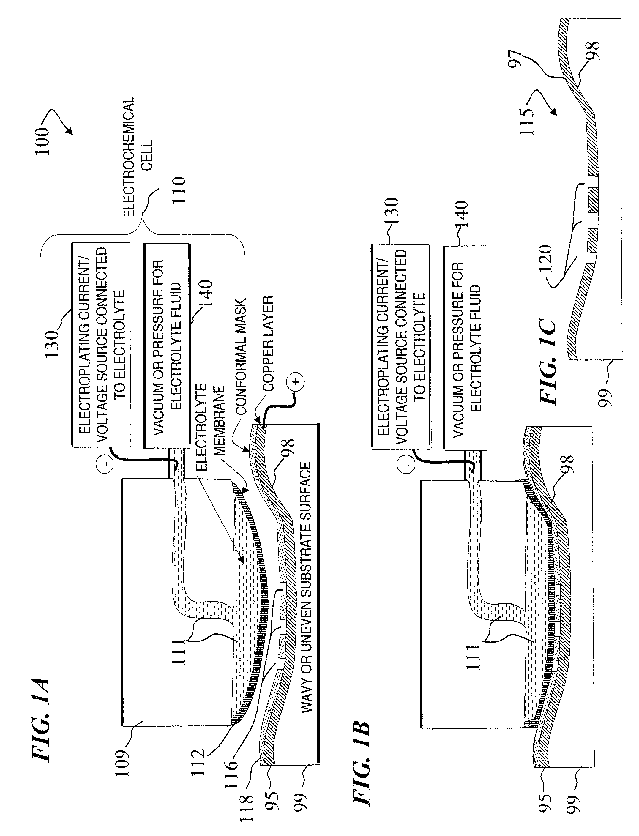
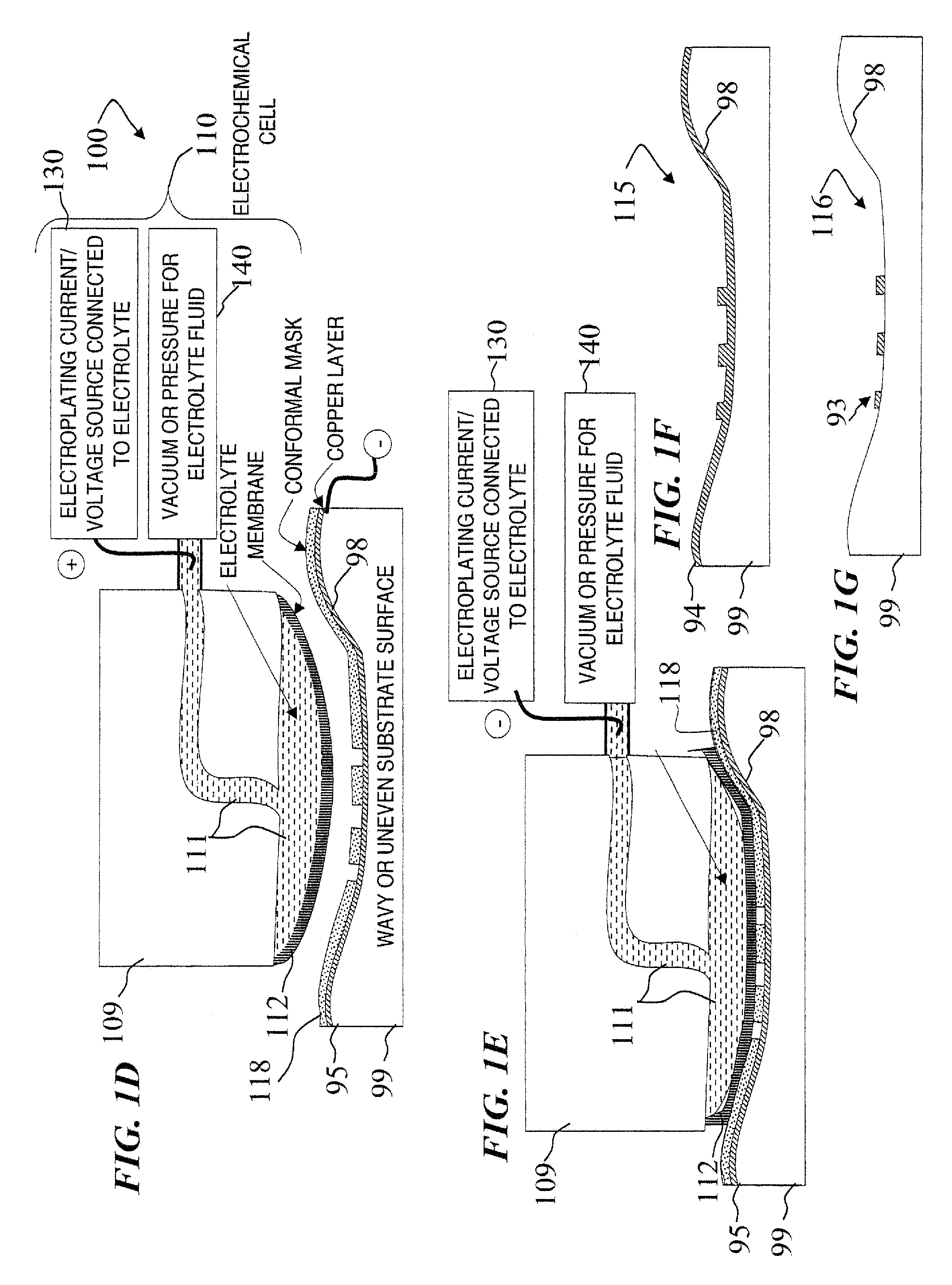
"The invention is a process called Focused Electric Field Imprinting (FEFI) which allows for the creation of very small patterns on copper and other electrically conductive surfaces. The process uses a curved membrane and electrodes to generate patterns around 20- 2000 microns in width and 0.1-10 microns in depth. By altering mask-membrane interaction parameters and process settings, the feature size can be significantly reduced and sub-100 nm features can be generated. The process is cost-advantaged compared to lithographic techniques and can be used on wavy surfaces. The device described in the patent application is also a factor of 10 to -100 less expensive than current Deep Ultraviolet (DUV) Steppers used for Lithography. The device can produce patterns in any shape and size and can be used for both circular and linear imprints."

Problems solved by technology

Unfortunately, we are rapidly approaching the limit of traditional processing methods for functionalizing and processing inexpensive miniaturized devices.
Clearly, a major challenge remains in the micro-manufacturing community to develop flexible, robust and large-scale fabrication methods that are economical and also environmentally friendly.
However, such processes are naturally limited by macro-scale phenomenon such as diffusion or thermal gradients.
Although subtraction processes such as electron or ion beam writing possess very high resolution capabilities for local patterning, they are sequential and cumbersome (due to macro-scale positioning requirements) with limitations in the materials they can modify and strict requirements of surface planarity.
Thus, direct extension of lithographic based fabrication facility, with its attendant high cost of ownership (COO) and the required capital outlay of upwards of $3 Billion are somewhat impractical for miniaturized components for targeting inexpensive and rapid throughput.
(2000) can achieve sub-100-nm patterning, but the equipment is expensive and requires planarized surfaces with roughness of the order of 0.1 times the wavelength of the ultraviolet light.
While they possess high material removal rate, these methods, however, are not suitable for very hard or very fragile, e.g., low dielectric porous materials.
In addition, they induce significant level of residual stresses, and possess additional limitations on dimensional tolerances and minimum gage requirements (Liu et al, 2004).
While the EC process has found major applications in IC fabrications such as in Damascene Cu Plating (Andricacos, 1999) and in electrochemical mechanical planarization of wafers (Steigerwald et al, 1997; Huo, et al 2004), most ECM processes, however, are not environmentally benign.
They also give rise to thermal and environmental concerns.
The finished surface comes in contact with corrosive chemicals, which may accelerate corrosion and necessitate post-ECM cleaning of the finished surface (Wilson, 1971).
Maintaining an ECM tool over a long period of time has also proved difficult.
However, it is only meant for polishing or planarization, and cannot imprint a specified pattern on a surface.
This makes surface preparation for such processes quite expensive, often requiring chemical mechanical planarization “CMP”.
Thus, capability for printing on wavy surfaces is also required for flexible IC devices, where performing CMP is very difficult.
The conventional available devices that can produce such patterns are expensive, and also typically require polished or planarized surfaces.

Method used


Image

  • Apparatus for focused electric-field imprinting for micron and sub-micron patterns on wavy or planar surfaces
  • Apparatus for focused electric-field imprinting for micron and sub-micron patterns on wavy or planar surfaces
  • Apparatus for focused electric-field imprinting for micron and sub-micron patterns on wavy or planar surfaces

Examples


Embodiment Construction

[0040]Although the following detailed description contains many specifics for the purpose of illustration, a person of ordinary skill in the art will appreciate that many variations and alterations to the following details are within the scope of the invention. Accordingly, the following preferred embodiments of the invention are set forth without any loss of generality to, and without imposing limitations upon the claimed invention.

[0041]In the following detailed description of the preferred embodiments, reference is made to the accompanying drawings that form a part hereof, and in which are shown by way of illustration specific embodiments in which the invention may be practiced. It is understood that other embodiments may be utilized, and that structural, sequential, and temporal changes may be made without departing from the scope of the present invention.

[0042]The leading digit(s) of reference numbers appearing in the Figures generally corresponds to the Figure number in which ...


PUM

PropertyMeasurementUnit
widthaaaaaaaaaa
smoothnessaaaaaaaaaa
thicknessaaaaaaaaaa

Abstract

A Focused Electric Field Imprinting (FEFI) process and apparatus provides a focused electric field to guide an unplating operation and / or a plating operation to form very fine-pitched metal patterns on a substrate. The process is a variation of the electrochemical unplating process, wherein the process is modified for imprinting range of patterns of around 2000 microns to 20 microns or less in width, and from about 0.1 microns or less to 10 microns or more in depth. Some embodiments curve a proton-exchange membrane whose shape is varied using suction on a backing fluid through a support mask. Other embodiments use a curved electrode. Mask-membrane interaction parameters and process settings vary the feature size, which can generate sub-100-nm features. The feature-generation process is parallelized, and a stepped sequence of such FEFI operations, can generate sub-100 nm lines with sub-100 nm spacing. The described FEFI process is implemented on copper substrate, and also works well on other conductors.

Description

CROSS-REFERENCE TO RELATED APPLICATION[0001]This application claims benefit under 35 U.S.C. 119(e) of U.S. Provisional Patent Application No. 60 / 804,163, filed on Jun. 7, 2006, titled “METHOD AND APPARATUS FOR FOCUSED ELECTRIC-FIELD IMPRINTING FOR MICRON AND SUB-MICRON PATTERNS ON WAVY OR PLANAR SURFACES,” which is incorporated herein by reference in its entirety.FIELD OF THE INVENTION[0002]The invention relates to the field of semiconductor manufacturing, and more specifically, the invention describes a new technique for electrochemical unplating or plating / deposition of micro and nano-scale patterns. The invention describes a procedure that is a potential substitute for lithography.BACKGROUND OF THE INVENTION[0003]There exist today several innovative manufacturing technologies to meet the demand for the production of components with features in the range of a sub-micron to several hundred micrometers. They are classified into two basic groups (Rajurkar et al, 2006): (i) lithograph...

Claims


Application Information

Patent Timeline
Patent Type & Authority Patents(United States)
IPC IPC(8): C25D17/00
CPCC25D5/22C25D17/00C25F3/02C25F3/14C25D5/02
Inventor CHANDRA, ABHIJITBASTAWROS, ASHRAF F.MITRA, AMBAR K.LEMAIRE, CHARLES A.
Owner ACTUS POTENTIA
Learn More