
Method and device for reducing laser phase noise

a laser and phase noise technology, applied in lasers, geological measurements, color/spectral properties measurements, etc., can solve the problems of low phase noise, low sensitivity to external vibration disturbance, narrow linewidth of conventional high-power telecom grade diode lasers, etc., to reduce laser signal phase noise and laser signal phase noise reduction

Inactive Publication Date: 2011-06-28
HE QING
View PDF17 Cites 4 Cited by
  • Summary
  • Abstract
  • Description
  • Claims
  • Application Information

AI Technical Summary

Benefits of technology

The solution effectively reduces phase noise by 20 to 40 dB in the low frequency range, enhancing the performance of fiber optic seismic sensing systems and other applications by stabilizing the laser wavelength and reducing sensitivity to external vibrations.

Problems solved by technology

The laser sources need to show not only low phase noise, but also low sensitivity to external vibration disturbance due to harsh environment.
Conventional high power telecom grade diode lasers exhibit narrow linewidth and low sensitivity to vibrations due to its small size.
But they exhibit high phase noise in the seismic sensors working frequency range, typically 1-1000 Hz.
Other types of lasers such as optical fiber lasers exhibit low phase noise but their phase noise increases dramatically in the field environment due to the sensitivity of the optical fiber (fiber length to be exact) to acoustic or mechanical vibrations (causing jitter and wavelength drift), which makes their use difficult without isolating the optical fiber lasers from harsh environmental disturbances.
These technical challenges and difficulties may hinder further development of fiber optic seismic sensing systems.

Method used


Image

  • Method and device for reducing laser phase noise
  • Method and device for reducing laser phase noise
  • Method and device for reducing laser phase noise

Examples


Embodiment Construction

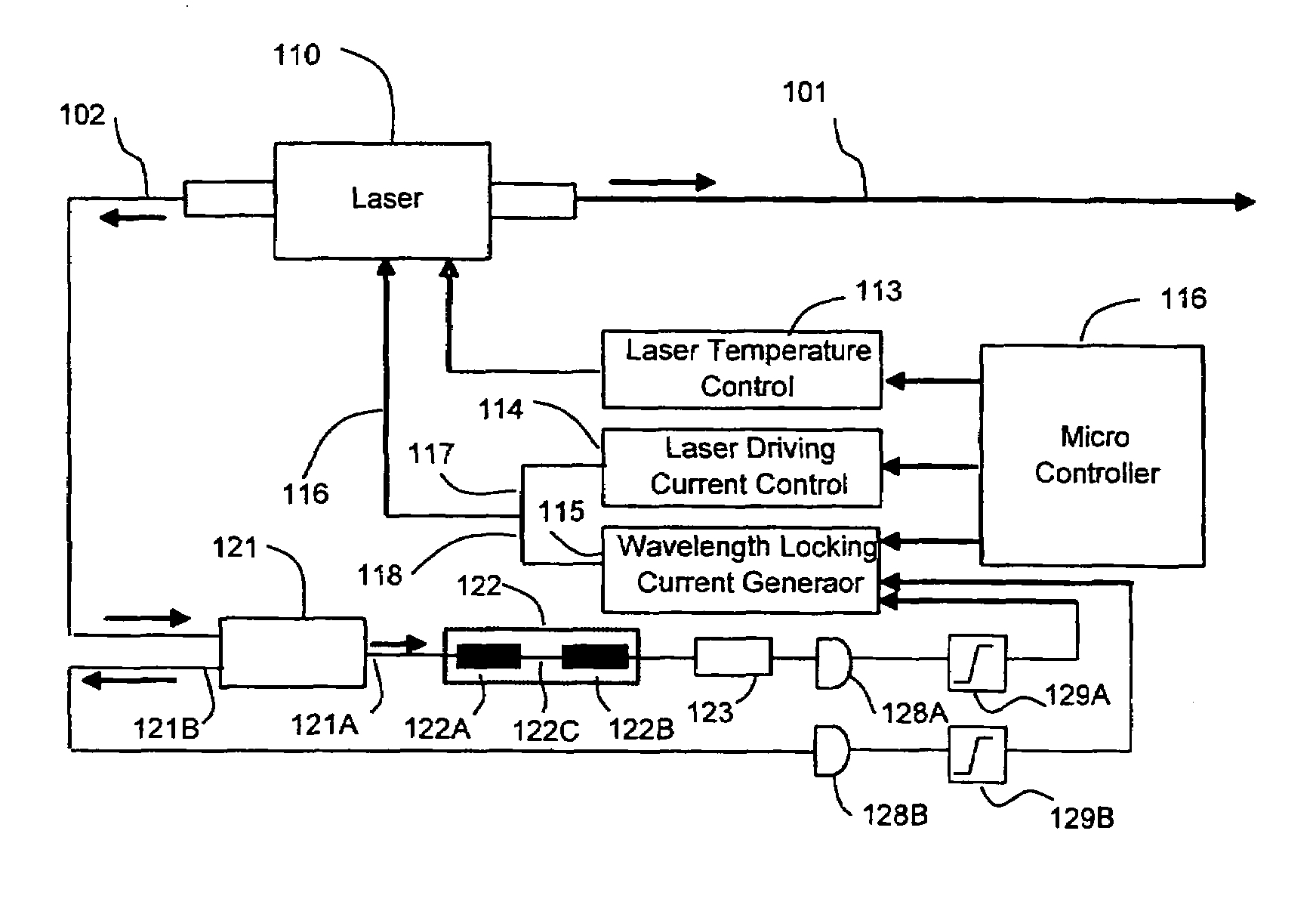
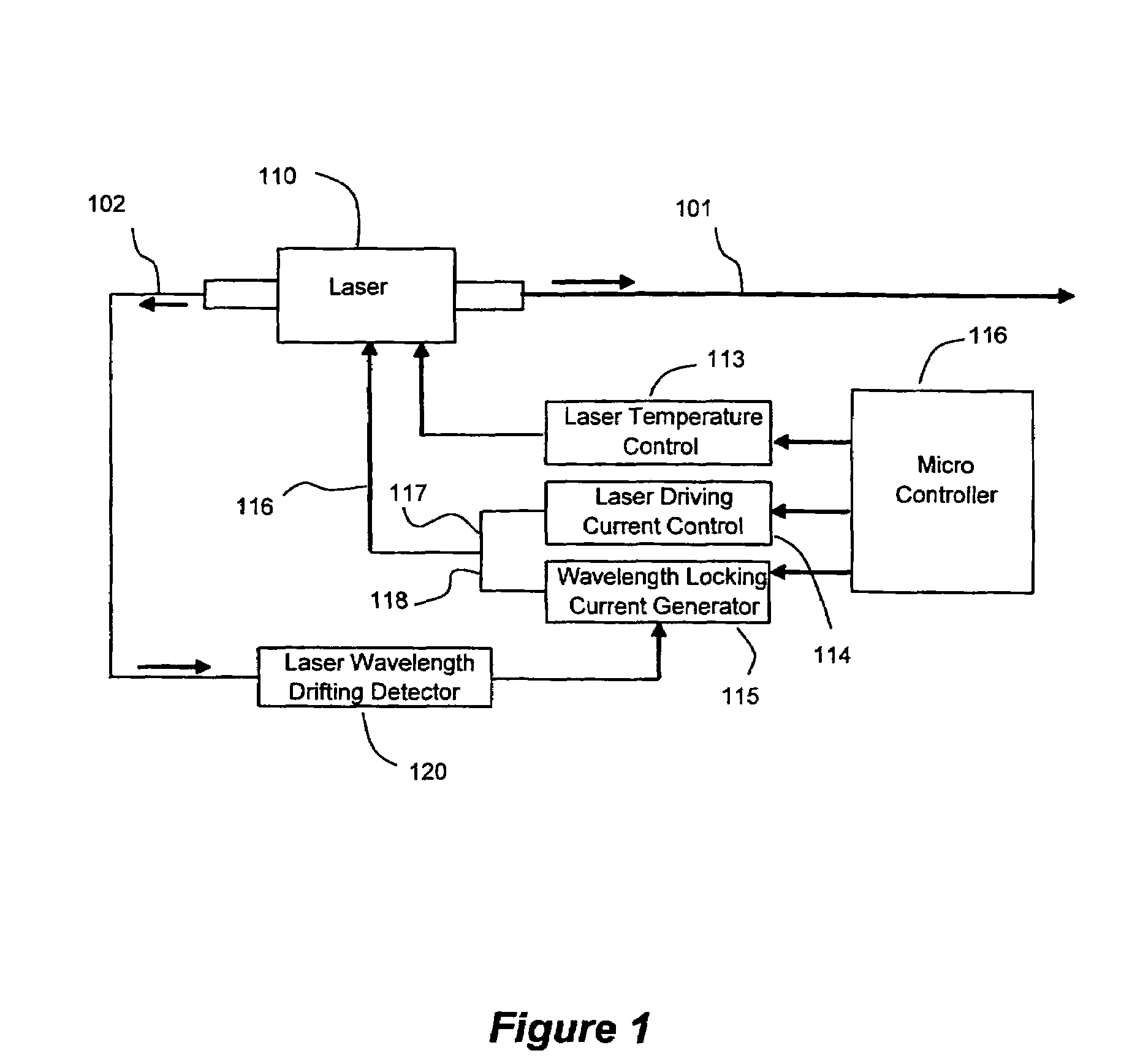
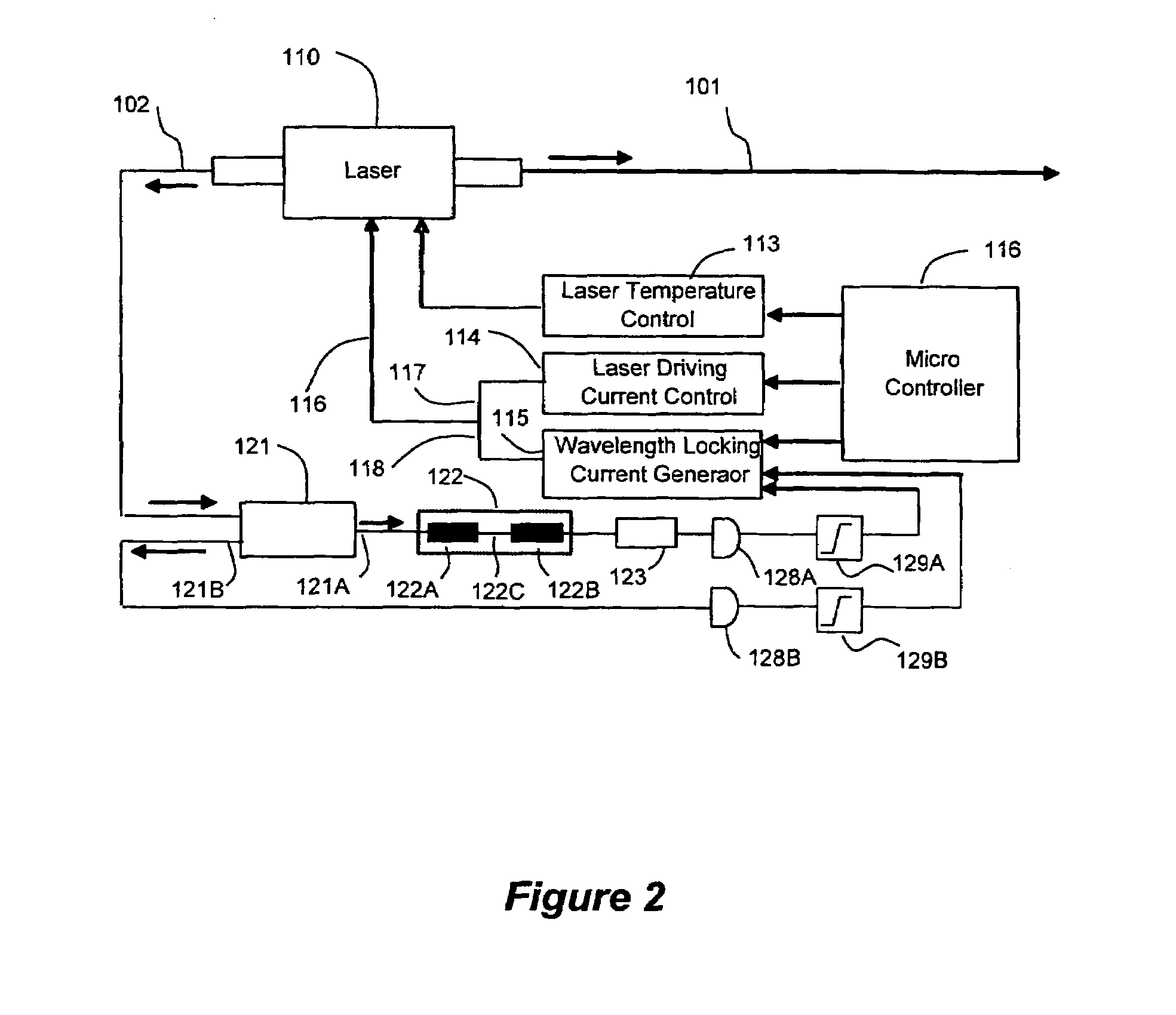
[0024]Laser phase noise at low frequency can be reduced by sending laser light into a high slope wavelength discrimination filter and convert wavelength drifting into intensity variation. By measuring the intensity variation with a photodiode and comparing the measured intensity variation with a laser reference intensity, a error signal is generated. Based on this error signal, a compensation current is generated and is then added to a laser source driving current. In this manner, the laser wavelength is locked within a bandwidth of the resulting laser phase stabilization loop. It is to be understood that depending on the polarity of the compensation current, the compensation current may increase or decrease the value of the laser source driving current.

[0025]Several elements are taken into account for designing the phase noise reduction loop and maximizing the loop performance.[0026]First, the phase noise characteristics of telecommunication grade laser diodes are different from ea...


PUM


Abstract

The present invention relates to a method and device for reducing the phase noise of a laser signal from a laser source. This device comprises a first current generator for supplying a driving current to the laser source in view of producing the laser signal. A phase noise detector is responsive to the laser wavelength for generating a phase error signal and a second current generator is responsive to the phase error signal for generating a compensation current added to the driving current supplied to the laser source for generating a phase-adjusted laser signal. The device therefore defines a phase stabilization loop formed by the phase noise detector and the second current generator, for reducing the phase noise of the laser signal.

Description

CROSS REFERENCE TO RELATED APPLICATIONS[0001]This application is the U.S. National Phase Application of International Patent Application Serial No. PCT / CA06 / 001673, filed Oct. 12, 2006, published under PCT Article 21(2) in English, which claims priority to and the benefit under 35 U.S.C. Section 119(e) of U.S. Provisional Patent Application Ser. No. 60 / 725,665, filed Oct. 13, 2005, the entire disclosures of each of which are incorporated by reference herein.FIELD OF THE INVENTION[0002]The present invention relates generally to a method and device for reducing phase noise of a laser source. More specifically, but not exclusively, the present invention relates to a method and device for effectively reducing the phase noise by 20 to 40 dB in the low frequency range of conventional distributed feedback diode laser and gain chip based external cavity laser (ECL), etc. for, as an example, fiber optic sensors based on interferometric principles, RF signal generation and coherent communicat...

Claims


Application Information

Patent Timeline
Patent Type & Authority Patents(United States)
IPC IPC(8): H01S3/00
CPCG01V1/181G02B6/29353H01S5/0683G02B6/29359H01S5/0687H01S5/06817
Inventor HE, QING
Owner HE QING
Learn More