
Articles comprising high-electrical-conductivity nanocomposite material and method for fabricating same

a nano-composite material and high-electrical-conductivity technology, applied in the field of composite materials, can solve the problems of significant and undesirable electron multiplication, reduce the surface's sensitivity to arc or sputtering damage, etc., and achieve good thermal conductivity, enhance mechanical strength, and minimize field enhancement

Inactive Publication Date: 2011-06-14
RGT UNIV OF CALIFORNIA
View PDF10 Cites 11 Cited by
  • Summary
  • Abstract
  • Description
  • Claims
  • Application Information

AI Technical Summary

Benefits of technology

This patent describes a new type of material that is strong, highly conductive, and resistant to fatigue. It is made by combining high-conductivity metal particles with high-conductivity dispersoid particles that minimize field enhancements and maintain good thermal conductivity. This material also reduces sensitivity to damage and has small electron emission coefficients. The use of metal nanoparticles with electrical conductivity comparable to that of the base automatically removes regions of higher RF field and enhanced current density. The technical effects of this patent are stronger, more conductive, and fatigue-resistant material structures that can be made using novel fabrication techniques.

Problems solved by technology

Additionally, conductive nanoparticles will reduce the surface's sensitivity to arc or sputtering damage.
Most importantly, the secondary electron emission coefficients of all materials in the nanocomposite are small and close to unity, whereas metals in the nanocomposite are small and close to unity, whereas the previously used insulating particles can produce significant and undesirable electron multiplication.

Method used


Image

  • Articles comprising high-electrical-conductivity nanocomposite material and method for fabricating same
  • Articles comprising high-electrical-conductivity nanocomposite material and method for fabricating same
  • Articles comprising high-electrical-conductivity nanocomposite material and method for fabricating same

Examples


Embodiment Construction

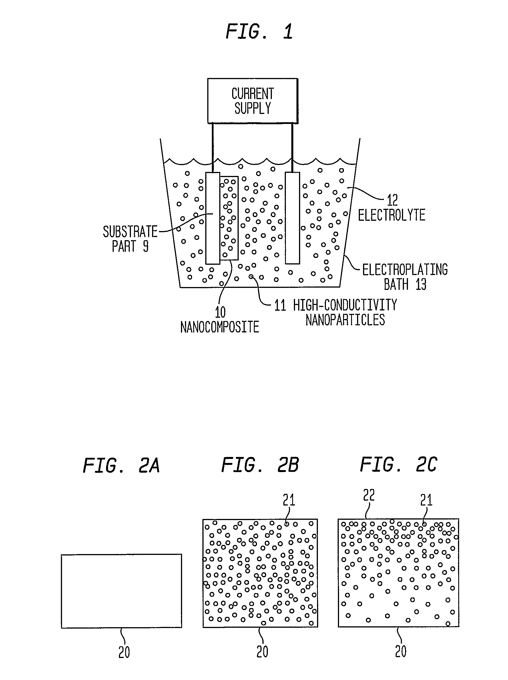
[0017]In order to achieve a nearly ideal material for high power microwave devices, applicant has provided a high conductivity composite with mechanically-strengthening nanoscale dispersoid particles that have electrical conductivity essentially matched with that of the base matrix metal. This invention can utilize any one of three types of dispersoids, the first being highly conductive metal nanoparticles artificially alloyed so that the matrix contains no or little dissolved dispersoid metal, the second being dispersoid nanoparticles made of high-conductivity, intermetallic compound, and the third being dispersoids comprising carbide, nitride, boride or carbon nanoparticles.

(a). Artificially Alloyed Metal Nanocomposites

[0018]In traditional precipitation-hardened Cu alloys employing high temperature metallurgical reactions, the electrical conductivity of the matrix metal [ρ(Cu)˜1.67 μΩ-cm] is significantly reduced by the solute atoms that do not completely precipitate. Any alloying...


PUM

PropertyMeasurementUnit
diameteraaaaaaaaaa
diameteraaaaaaaaaa
volume fractionaaaaaaaaaa

Abstract

This invention discloses novel nanocomposite material structures which are strong, highly conductive, and fatigue-resistant. It also discloses novel fabrication techniques to obtain such structures. The new nanocomposite materials comprise a high-conductivity base metal, such as copper, incorporating high-conductivity dispersoid particles that simultaneously minimize field enhancements, maintain good thermal conductivity, and enhance mechanical strength. The use of metal nanoparticles with electrical conductivity comparable to that of the base automatically removes the regions of higher RF field and enhanced current density. Additionally, conductive nanoparticles will reduce the surface's sensitivity to arc or sputtering damage. If the surface is sputtered away to uncover the nanoparticles, their properties will not be dramatically different from the base surface. Most importantly, the secondary electron emission coefficients of all materials in the nanocomposite are small and close to unity, whereas the previously used insulating particles can produce significant and undesirable electron multiplication.

Description

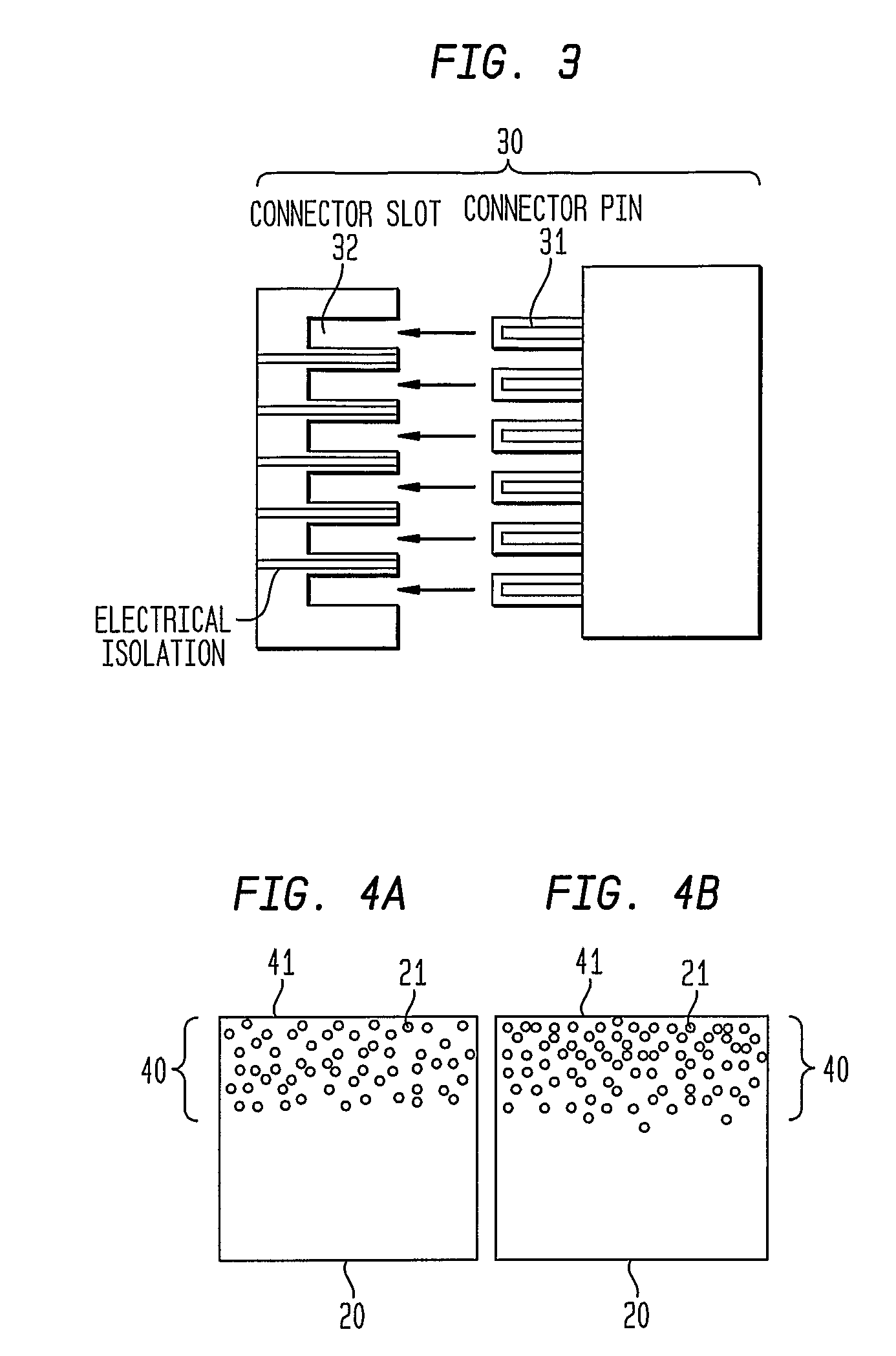
CROSS REFERENCE TO RELATED APPLICATIONS[0001]This application is a U.S. National Stage Application of PCT Application No. PCT / US2004 / 043458, filed on Dec. 23, 2004, which in turn claims the benefit of U.S. Provisional Application Ser. No. 60 / 533,618 entitled “Articles Comprising High-Electrical Conductivity Nanocomposite Material and Method for Fabricating Same”, filed by Sungho Jin on Dec. 31, 2003. The entire disclosures of PCT Application No. PCT / US2004 / 043458 and U.S. Provisional Application No. 60 / 533,618 are hereby incorporated herein by reference.FIELD OF INVENTION[0002]The present invention relates to articles comprising composite materials. In particular, it provides articles comprising bodies of strong, highly conductive nanocomposite materials useful for conducting electrical current at high power levels. Such articles are particularly useful for enhancing the performance of devices such as high power microwave devices, electrical connectors and electrical contacts.BACKGR...

Claims


Application Information

Patent Timeline
Patent Type & Authority Patents(United States)
IPC IPC(8): H01B1/02B22F3/00H01L21/763B32B3/02B22F1/054C22C47/04C25D5/48C25D15/02H01L23/373
CPCB22F1/0018B82Y30/00C22C47/04C25D5/48C25D15/02H01B1/026Y10T428/12049B22F2998/10B22F2999/00H01L23/3732B22F2998/00Y10T428/26Y10T428/12493Y10T428/12576Y10T428/2991Y10T428/12771Y10T428/25H01L2924/0002B22F2207/03B22F1/025B22F1/0085B22F3/02B22F3/10B22F2201/01H01L2924/00B22F1/054B22F1/18B22F1/142
Inventor JIN, SUNGHO
Owner RGT UNIV OF CALIFORNIA
Learn More