
Threaded joint for steel pipe

a technology of threaded joints and steel pipes, which is applied in the direction of screw threaded joints, hose connections, mechanical equipment, etc., to achieve the effect of enhancing gas tightness and preventing rus

Inactive Publication Date: 2011-01-11
VALLOUREC OIL & GAS FRANCE SAS
View PDF51 Cites 11 Cited by
  • Summary
  • Abstract
  • Description
  • Claims
  • Application Information

AI Technical Summary

Benefits of technology

[0010]An object of the present invention is to provide a threaded joint for a steel pipe which can suppress galling at repeated fastening or loosening without using a liquid lubricant containing a heavy metal powder such as a compound grease and a solid lubricant film containing a harmful substance which are feared to have adverse effect on the earth environment or a human body, and is excellent in galling resistance, and a process for manufacturing the same.
[0024]The threaded joint for a steel pipe of the present invention has no or little harmfulness on a human body and the environment as compared with the previous liquid lubricant containing a heavy metal powder such as a compound grease and the previous solid lubricating film. In addition, according to the threaded joint for a steel pipe of the present invention, and the process for manufacturing the same, rust preventing property and gas tightness can be enhanced, galling at repeated fastening or loosening can be suppressed, and the effect is maintained even at a high temperature.

Problems solved by technology

As explained above, a threaded joint which can be repeatedly used without adversely influencing on the earth environment such as marine organisms and human body, and is excellent in galling resistance has not been obtained now.

Method used


Image

  • Threaded joint for steel pipe
  • Threaded joint for steel pipe
  • Threaded joint for steel pipe

Examples


example 1

[0072]A threaded joint made of a carbon steel having a composition A shown in Table 1 was subjected to the following surface treatment A box surface was subjected to mechanical grinding finishing (surface roughness 3 μm), and a solid lubricating film having a thickness of 30 μm comprising an epoxy resin containing a graphite powder having an average particle diameter of 5 μm and a copper powder having a maximum length of 15 μm which had been inactivated by surface treatment was formed thereon. A solid lubricating film was a film containing 0.6 of graphite relative to 1 of an epoxy resin, and 1.2 of a copper powder relative to 1 of graphite expressed by a mass ratio. After formation of the solid lubricating film, this was heat-treated at 180° C. for 30 minutes to harden the film. A pin surface was subjected to only mechanical grinding finishing (surface roughness 3 μm). In a fastening and loosening test, a galling did not occur in ten times fastening and loosening in Table 5, being e...

example 2

[0073]A threaded joint made of a Cr—Mo steel having a composition B shown in Table 1 was subjected to the following surface treatment. A box surface was subjected to mechanical grinding finishing (surface roughness 3 μm), then, a surface thereof was immersed in a manganese phosphate chemical treating solution at 80 to 95° C. for 10 minutes to form a manganese phosphate film having a thickness of 15 μm on the surface, and a solid lubricant film having a thickness of 15 μm comprising an epoxy resin containing a graphite powder having an average particle diameter of 10 μm and a copper powder having a greatest length of 15 μm was further formed thereon. The solid lubricating film was a film containing 1 of graphite relative to 1 of an epoxy resin, and 0.5 of a copper powder relative to 1 of graphite expressed by a mass ratio. After formation of a solid lubricating film, this was heat-treated at 180° C. for 30 minutes to harden a film. A pin surface was subjected to mechanical grinding f...

example 3

[0074]A threaded joint made of a 13Cr steel having a composition C shown in Table 1 was subjected to the following surface treatment. A No. 80 sand was blown to a box surface to adjust surface roughness to 10 μm, copper plating having a thickness of about 5 μm was formed thereon, and a solid lubricating film having a thickness of 20 μm comprising an epoxy resin containing a mica powder having an average particle diameter of 2 μm and a copper powder having a greatest length of 10 μm was further formed thereon. The solid lubricating film was a film containing 2 of mica relative to 1 of an epoxy resin, and 1 of a copper powder relative to 1 of mica expressed by a mass ratio. After formation of the solid lubricating film, this was heat-treated at 180° C. for 30 minutes to harden the film. A pin surface was subjected to only mechanical grinding finishing (surface roughness 3 μm). In a fastening and loosening test, a galling did not occur in ten times fastening and loosening in Table 5, b...


PUM

PropertyMeasurementUnit
lengthaaaaaaaaaa
depthaaaaaaaaaa
depthaaaaaaaaaa

Abstract

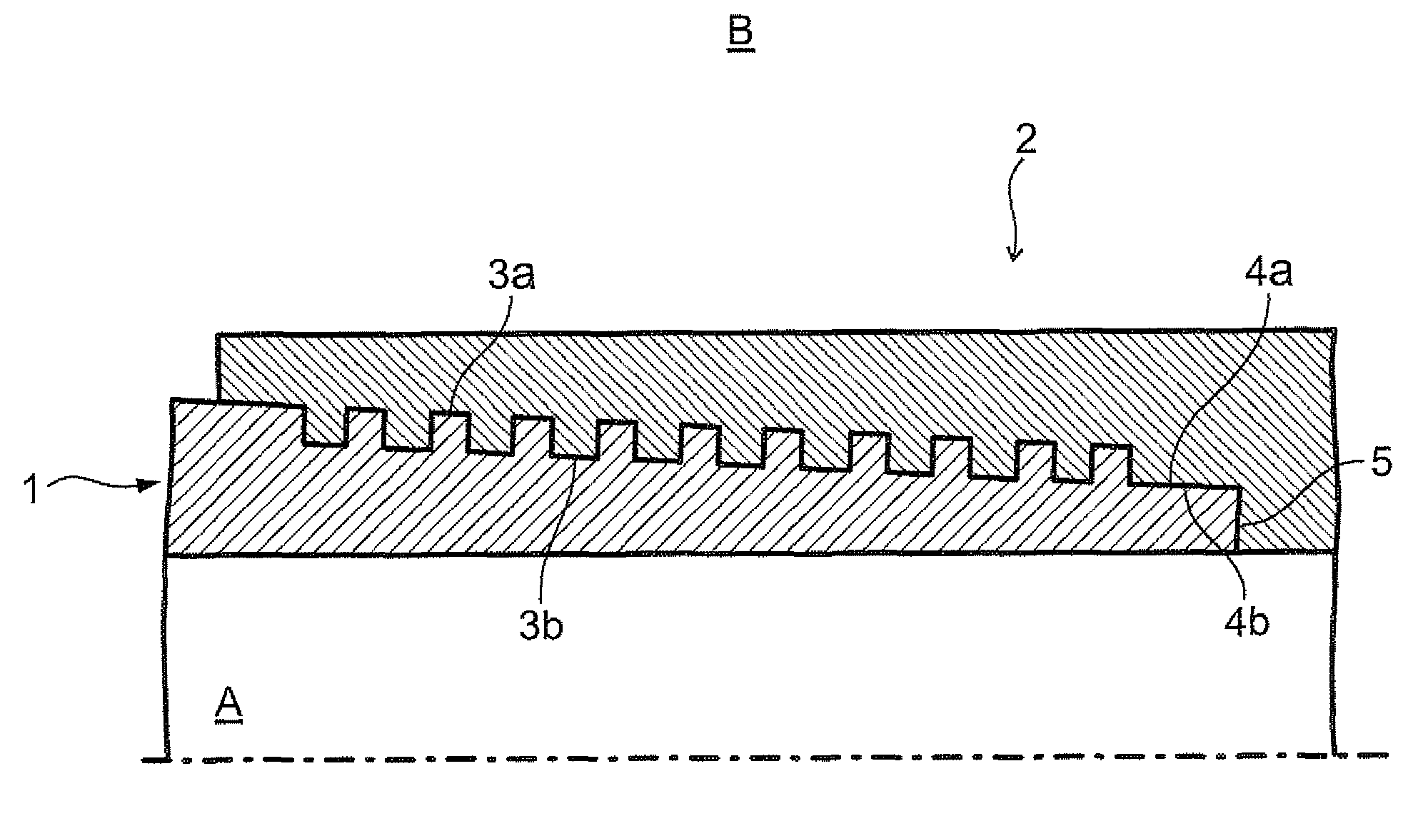
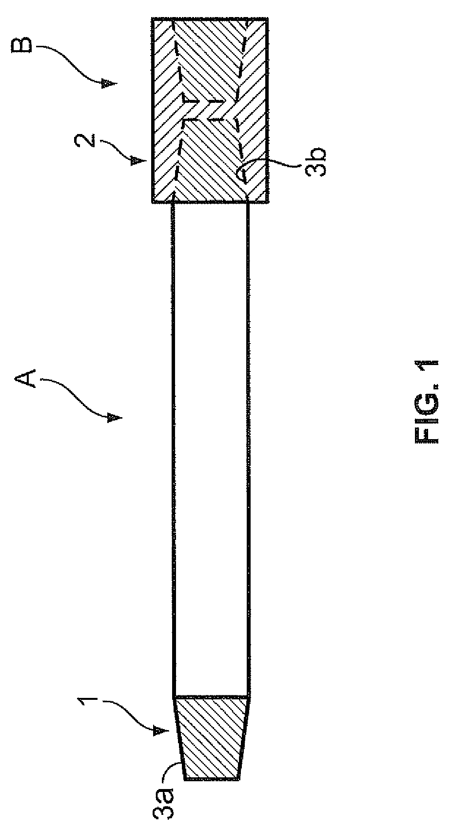
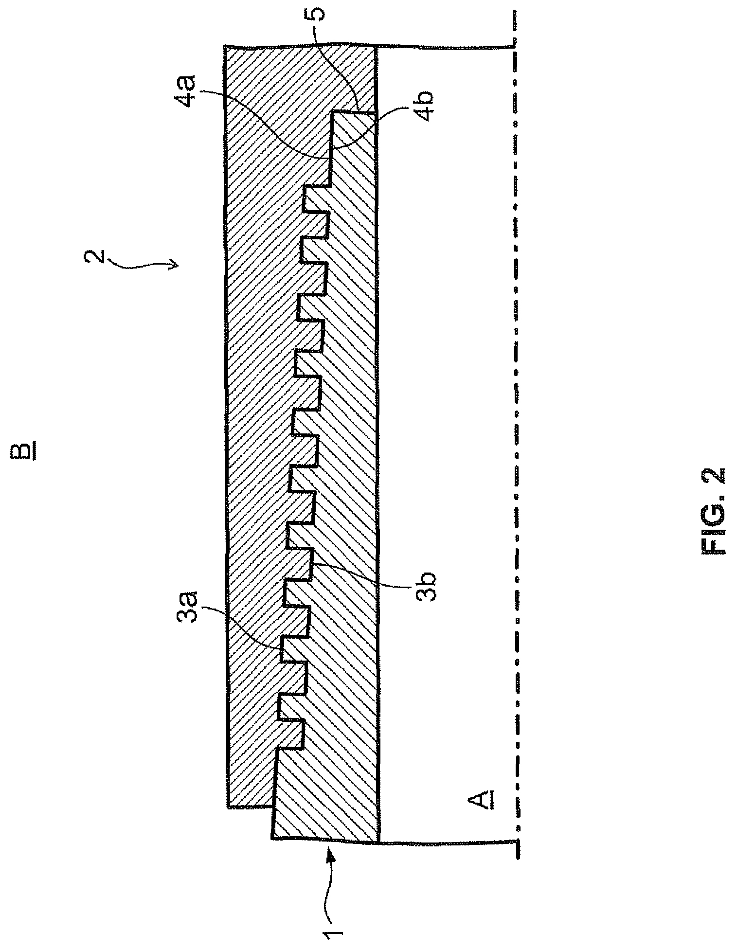
A threaded joint for a steel pipe comprises a pin and a box with a contact surface having a threaded part and a unthreaded metal contact part, wherein a solid lubricating film containing one or more kinds of lubricating powders selected from graphite, mica, calcium carbonate and kaolin, a copper powder, and a binder is formed on at least one contact surface of the pin and the box. An object of the present invention is to provide a threaded joint for a steel pipe which allows for repeated fastening and loosening of a threaded joint without adversely influencing on a human body and environment, and is excellent in galling resistance, rust preventing property and gas tightness.

Description

TECHNICAL FIELD[0001]The present invention relates to a screw joint (threaded joint) for a steel pipe which can be used without coating a compound grease which has conventionally been used upon fastening of a threaded joint for an oil well pipe and, at the same time, does not adversely affect on the earth environment and a human body, and is excellent in galling resistance, and a process for manufacturing the same.BACKGROUND ART[0002]In a tubing and a casing used in digging an oil well, a threaded joint is generally used. Usually, a depth of an oil well is 2000 m to 3000 m. However, in a deep oil well such as a marine oil field in recent years, a depth of an oil well reaches 8000 m to 10000 m. An axial tensile force due to a weight of an oil well pipe and a joint themselves and a pressured which is complexed of an internal and external pressure, and heat in the ground exert on a threaded joint for fastening these oil well pipes under the use environment. Therefore, a threaded joint ...

Claims


Application Information

Patent Timeline
Patent Type & Authority Patents(United States)
IPC IPC(8): F16L15/00F16L15/04C10M103/00C10M103/02C10M103/04C10M103/06C10M125/00C10M145/20C10M149/18C10N10/02C10N10/04C10N40/00C10N50/08C10N80/00E21B17/00E21B17/042F16L15/08
CPCC10M103/00C10M125/00E21B17/006E21B17/042F16L15/001F16L15/006F16L15/08F16L58/182C10M2201/041C10M2201/05C10M2201/062C10M2201/066C10M2201/103C10N2240/00C10N2250/08C10N2280/00C10N2040/00C10N2050/08C10N2080/00
Inventor GOTO, KUNIOIMAI, RYUICHIOGAWA, YASUHIROMINAMI, JUNICHI
Owner VALLOUREC OIL & GAS FRANCE SAS
Learn More