
Duty cycle correction methods and circuits

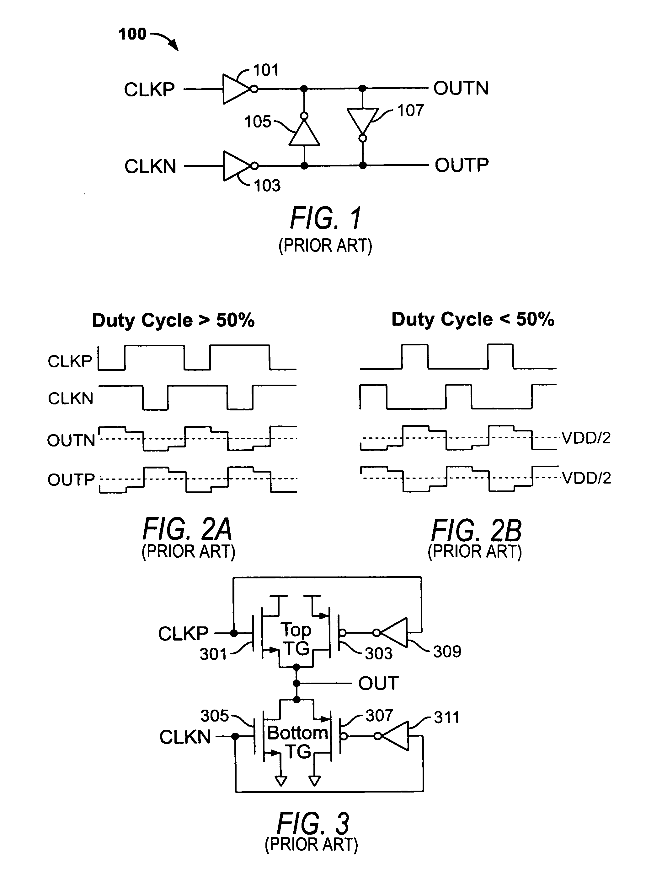
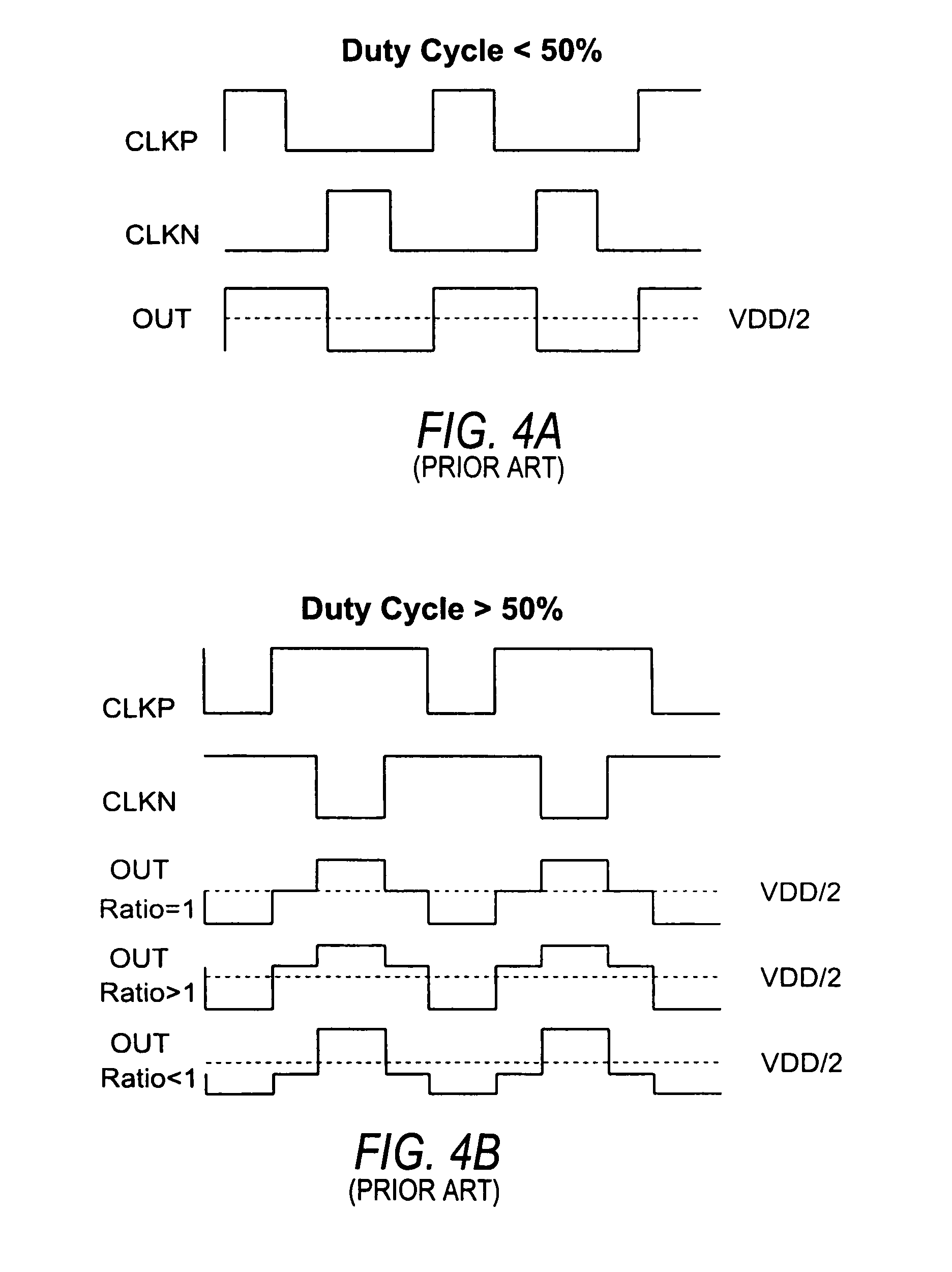
a duty cycle and circuit technology, applied in the direction of generating/distributing signals, pulse techniques, instruments, etc., can solve the problems of introducing stability problems in the circuit, circuits may function improperly, and circuits may be more complicated, so as to reduce the size and performance requirements of individual stages.

Inactive Publication Date: 2010-11-23
ALTERA CORP
View PDF4 Cites 25 Cited by
  • Summary
  • Abstract
  • Description
  • Claims
  • Application Information

AI Technical Summary

Benefits of technology

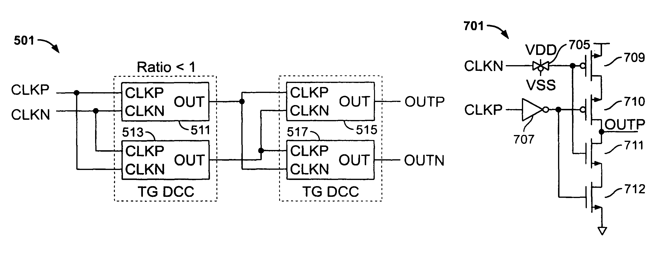
[0007]Clocked CMOS DCC circuits are operative to correct the duty cycle of signals over a wide range of input signal duty cycles. The clocked CMOS DCC circuits include as few as four transistors for single-ended operation, and as few as eight transistors for producing a fully differential output signal. The circuits consume limited amounts of current by eliminating the short-circuit currents which typically flow through other known DCC circuits.
[0008]Multi-stage DCC circuits make use of known DCC circuits coupled in series for their operation. Individual stages may include cross-coupled inverter DCC or transmission gate DCC circuits, for example. The multi-stage DCC circuits provide accurate duty cycle correction over wider ranges of input duty cycles, as compared to their single stage counterparts. In addition, the sizing and performance requirements of the individual stages are greatly reduced, ensuring that the multi-stage DCC circuits function properly despite fabrication or other variations in the circuits.

Problems solved by technology

If the duty cycle of the clock signal in these circuits is not equal to 50%, the circuits may function improperly due to timing errors.
However, they require more complicated circuitry and may introduce stability problems in the circuit.

Method used


Image

  • Duty cycle correction methods and circuits
  • Duty cycle correction methods and circuits
  • Duty cycle correction methods and circuits

Examples


Embodiment Construction

[0019]Duty cycle correction (DCC) circuitry may be used to correct the duty cycle of clock signals at any location in an integrated circuit. DCC circuitry may be especially effective in correcting the duty cycle of clock signals and improving circuit operation when located near high-speed circuit components that require precise timing and synchronization information. DCC circuitry may also be effective to improve the quality of clock signals which have traveled along long wires, traces, I / O pins, or other interconnection conductors, through clock processing circuitry, I / O circuitry, or other types of circuitry, or clock signals which may have suffered from deterioration, skew, or distortion.

[0020]The DCC circuitry and the circuitry controlled by the corrected clock may be implemented on one or more integrated circuits, on programmable logic devices, or in other types of circuitry. The corrected clock signal may be used to control the operation of one or more processors, digital sign...


PUM


Abstract

Duty cycle correction (DCC) methods and circuits are provided for improving the quality of clock signals and reducing or eliminating duty cycle distortion. The performance of known duty cycle correction circuits, such as cross-coupled inverter or transmission gate DCC circuits, may be improved by coupling two or more DCC circuits in series to form a multi-stage DCC circuit. In multi-stage DCC circuits, the performance and sizing requirements imposed on the individual circuit stages are reduced as compared to single-stage DCC circuit implementations. Good duty cycle correction performance over a wide range of input signal duty cycles may therefore be ensured regardless of the performance of individual stages. Clocked-CMOS DCC circuits are also presented, the circuits operative to produce duty cycle corrected output signals while consuming minimal current and power. The clocked-CMOS DCC circuits include as few as four transistors, and are operative over wide ranges of input signal duty cycles.

Description

BACKGROUND OF THE INVENTION[0001]This invention relates to duty cycle correction (DCC) methods and circuitry. Feed-forward duty cycle correction methods and circuits are used to recover or improve the quality of clock signals. Such methods and circuitry may be used at any stage in the clock path to improve the quality of the clock signal.[0002]The duty cycle of a clock signal is the ratio of the pulse duration to the pulse period. A clock signal with 50% duty cycle is therefore in a HIGH logic state for half of the signal period, and in a LOW logic state for the other half of the signal period. Signals that are HIGH for more than half of the signal period have duty cycles above 50%, while signals that are LOW for more than half of the signal period have duty cycles below 50%.[0003]High-speed circuits that use both the rising and falling edges of the clock signal for timing require clock signals that have 50% duty cycle. Circuits that rely on both clock edges include double-data rate...

Claims


Application Information

Patent Timeline
Patent Type & Authority Patents(United States)
IPC IPC(8): H03K3/017
CPCH03K5/1565
Inventor WANG, SHOUJUN
Owner ALTERA CORP
Learn More