Plasma-based EUV light source

a technology of ultraviolet light and plasma, which is applied in the field of plasma-based extreme ultraviolet (euv) light sources, can solve the problems of operation at such extremely short wavelengths

Inactive Publication Date: 2010-11-02
UNIV OF WASHINGTON
View PDF14 Cites 6 Cited by
  • Summary
  • Abstract
  • Description
  • Claims
  • Application Information

AI Technical Summary

Problems solved by technology

Operation at such extremely short wavelengths, presents a number of problems.
Some of these problems have to do with optical absorption, requiring the use of reflective materials instead of refractive ones; others have to do with optical contamination, requiring a vacuum environment.
Still other problems arise in power production, where an EUV source cannot produce but a fraction of the suggested manufacturing power output, which may be on the order of at least 100 watts of power at the entrance of the optics system or intermediate focus.

Method used


Image

  • Plasma-based EUV light source
  • Plasma-based EUV light source
  • Plasma-based EUV light source

Examples


Embodiment Construction

[0021]Various aspects of the subject matter illustrated in FIGS. 1A-4 are described in more detail directly below. First, general aspects of a device configured to produce sheared plasma flow are considered, followed by a discussion of an exemplary process or method of producing EUV light based on such sheared plasma flow. Lastly, a system for using such EUV light is considered, where the system is used in lithography.

Aspects of Light Source Configured for Producing EUV Light

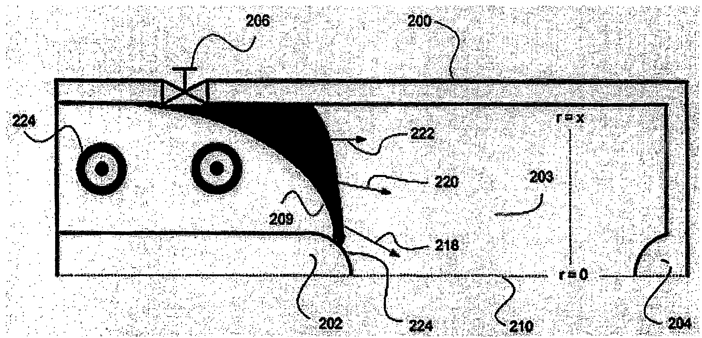
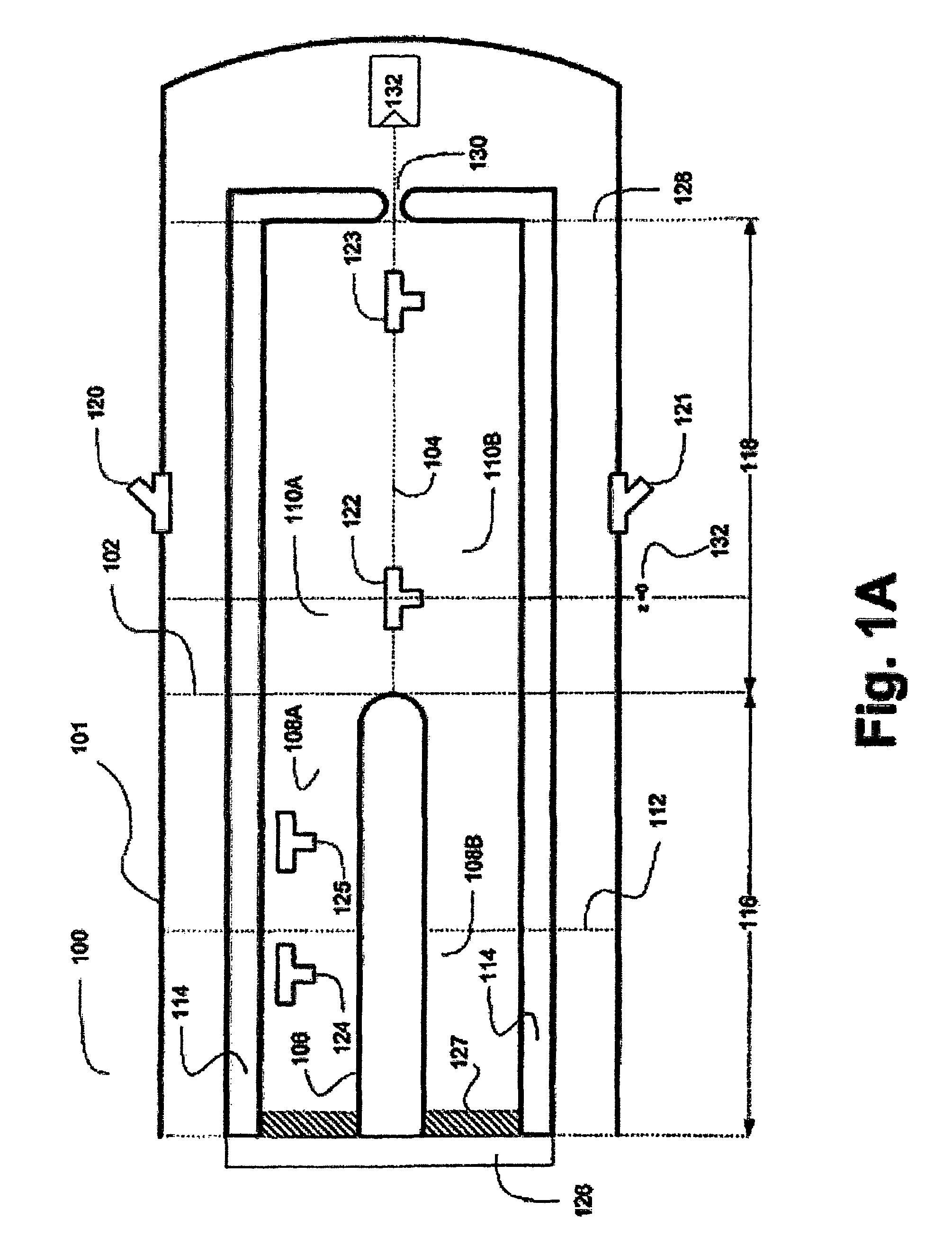
[0022]Various mechanisms may be used for producing EUV Light. In one aspect of the presently disclosed subject matter, a “Z-pinch”100 is shown in FIG. 1A. The Z-pinch 100 is a type of plasma confinement system that relies on the Lorentz force to “pinch” or compress the plasma to high temperatures. For example, such a confinement system 100 may be a vacuum vessel 101 that contains the plasma.

[0023]According to FIG. 1A, the Z-pinch 100 may comprise of two regions: an acceleration region 116 and an assembly region ...


PUM


Abstract

Various mechanisms are provided relating to plasma-based light source that may be used for lithography as well as other applications. For example, a device is disclosed for producing extreme ultraviolet (EUV) light based on a sheared plasma flow. The device can produce a plasma pinch that can last several orders of magnitude longer than what is typically sustained in a Z-pinch, thus enabling the device to provide more power output than what has been hitherto predicted in theory or attained in practice. Such power output may be used in a lithography system for manufacturing integrated circuits, enabling the use of EUV wavelengths on the order of about 13.5 nm. Lastly, the process of manufacturing such a plasma pinch is discussed, where the process includes providing a sheared flow of plasma in order to stabilize it for long periods of time.

Description

CROSS-REFERENCE TO RELATED APPLICATION[0001]This application is a continuation-in-part of U.S. application Ser. No. 11 / 252,021 filed Oct. 17, 2005, which is incorporated by reference in its entirety.STATEMENT OF GOVERNMENT SUPPORT[0002]This invention was made by government support by U.S. Department of Energy Grant No. DE-FG03-98-ER54460. The Government has certain rights in this invention.TECHNICAL FIELD[0003]The presently disclosed subject matter relates to the providing of a plasma-based extreme ultraviolet (EUV) light source. More specifically, it relates to the applicability of such a light source in, for example, lithography.BACKGROUND OF THE INVENTION[0004]Lithography is used in the manufacture of integrated circuits. It is used to transfer circuit patterns from a mask to silicon (or other equivalent and alternative) surfaces. In recent times, for optical lithography at least, the characteristic wavelength has decreased from 365 nm (nanometers) to 248 nm to 193 nm and is curr...

Claims


Application Information

Patent Timeline
Patent Type & Authority Patents(United States)
IPC IPC(8): A61N5/06
CPCH05G2/003
Inventor SHUMLAK, URIGOLINGO, RAYMONDNELSON, BRIAN A.
Owner UNIV OF WASHINGTON
Why Eureka
Try Eureka