Adaptive keeper circuit to control domino logic dynamic circuits using rate sensing technique

a dynamic circuit and keeper circuit technology, applied in the direction of power consumption reduction, pulse technique, instruments, etc., can solve the problems of large degradation of chip performance, affecting the yield of chips, and prone to leakage and other coupling noises, so as to reduce contention, reduce power and delay, and reduce the overhead in area

Inactive Publication Date: 2010-09-28
INDIAN INSTITUTE OF SCIENCE
View PDF1 Cites 5 Cited by
  • Summary
  • Abstract
  • Description
  • Claims
  • Application Information

AI Technical Summary

Benefits of technology

[0025]Yet another object of the present invention relates to provide an adaptive keeper circuit to control Domino Logic Dynamic Circuits using Rate Sensing Technique to provide reduced contention and efficient process tracking at a given noise robustness with less overhead in area, power and delay.
[0026]Still another object of the present invention is an adaptive keeper technique which ensures that the keeper is OFF at the start of the evaluation phase resulting in reduced contention and high speed.

Problems solved by technology

This in turn affects the yield of the chips, that meet certain performance specification.
However this is too pessimistic and will result in a large degradation in the performance of the chip.
The major challenge in circuit design lies in controlling these devices selectively and adapting them to work efficiently in a specific process corner.
Thus when the node is floating high in evaluation phase, it is susceptible to leakage and other coupling noises.
However in technologies below 130 nm, the leakage current has increased tremendously and the variation in the device threshold has also gone up.
In case of wider gates if the keeper is sized for the worst case leakage it can result in a situation where the contention current exceeds the on current of a single NMOS and prevent the node from switching.
This causes the delay of the dynamic gate to increase exponentially.
The keeper upsizing also has a severe impact on the power.
Excess power is wasted in the keeper due to a large contention current and in the feedback inverter due to short circuit current because of the longer fall time of the dynamic node voltage.
The conventional keeper cannot be used for wider pull-down legs because the keeper size required to maintain the robustness is too huge that during evaluation the logic fails to switch due to the larger contention current.
Thus upsizing the keeper is certainly not the right way for achieving robustness.
This technique still has the problem of contention and also a large area overhead to generate the corner information.
However in the conditional keeper technique, the keeper is weak during the output transition window and strong for the rest of the evaluation time, if the dynamic node should remain high.
1. The conventional keeper design results in huge contention current and lacks process tracking.
This has limited the number of pull-down legs in the nano-CMOS technologies.
Also since the keeper dimensions are fixed, finer control of the keeper current is not possible.
Moreover this technique does not track the dynamic variations in temperature and noise.
3. The conditional keeper technique [4], although reduces the contention current by delaying the clock to the strong keeper, lacks process tracking.
However in a given process corner the amount of contention is still high due to the feedback keeper.
5. The feedback keeper technique in general results in a lot of short circuit power dissipation in the keeper PMOS and also in the feedback inverter.
If a single current mirror is used for the entire design then it can result in variation in the bias currents.

Method used


Image

  • Adaptive keeper circuit to control domino logic dynamic circuits using rate sensing technique
  • Adaptive keeper circuit to control domino logic dynamic circuits using rate sensing technique
  • Adaptive keeper circuit to control domino logic dynamic circuits using rate sensing technique

Examples


Embodiment Construction

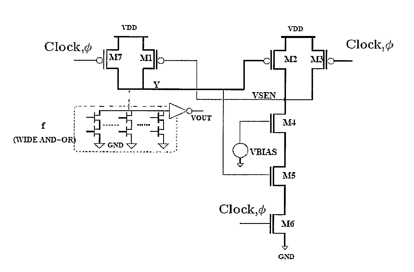
[0029]The primary embodiment of the present invention is an adaptive keeper circuit to control Domino Logic Dynamic Circuits using Rate Sensing Technique to provide reduced contention and efficient process tracking at a given noise robustness with less overhead in area, power and delay, said adaptive keeper comprising, keeper PMOS transistor (M1), wherein the drain of M1 is connected to wide AND-OR logic circuit; the rate controller consisting of reference rate transistor (M4), feedback PMOS transistor (M2), feedback shutoff transistor (M5), clock shutoff transistor (M6), pre-charge PMOS transistor (M3), wherein the input of the rate controller is directly connected to drain of the keeper PMOS (M1) and the output of the rate controller is directly connected to the gate of the PMOS keeper (M1),

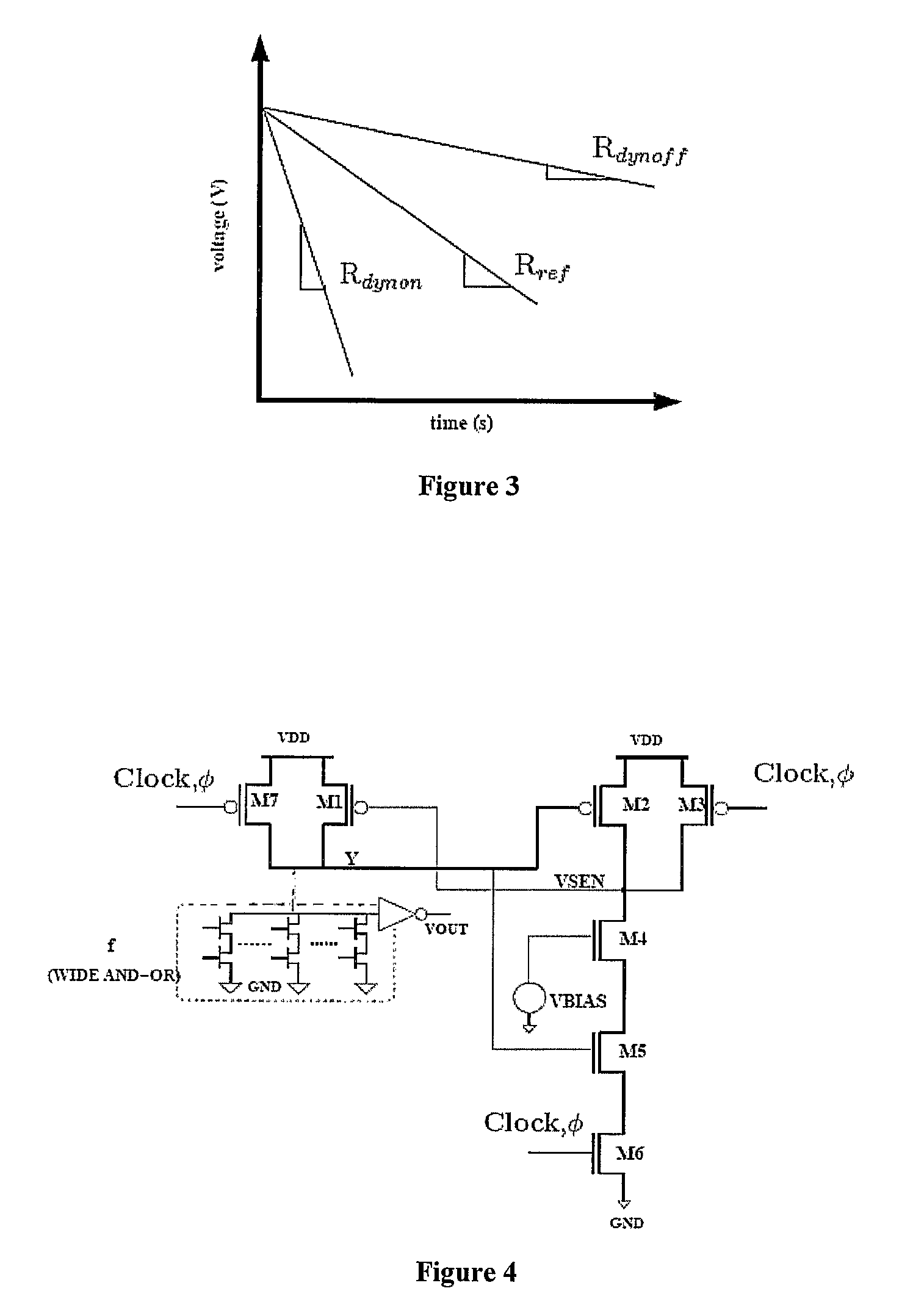
[0030]In yet another embodiment of the present invention, the technique exploits the differential rate of change of output for two cases preferably logic 0 and logic 1.

[0031]In still another em...


PUM


Abstract

The present invention provides an adaptive keeper circuit to control Domino Logic Dynamic Circuits using Rate Sensing Technique to provide reduced contention and efficient process tracking at given noise robustness with less overhead in area, power and delay, said adaptive keeper comprising, keeper PMOS transistor (M1), wherein the drain of M1 is connected to wide AND-OR logic circuit; the rate controller consisting of reference rate transistor (M4), feedback PMOS transistor (M2), feedback shutoff transistor (M5), clock shutoff transistor (M6), pre-charge PMOS transistor (M3), wherein the input of the rate controller is directly connected to drain of the keeper PMOS (M1) and the output of the rate controller is directly connected to the gate of the PMOS keeper (M1).

Description

FIELD OF THE INVENTION[0001]The present invention relates to an adaptive keeper circuit to control Domino Logic Dynamic Circuits using Rate Sensing Technique to provide reduced contention and efficient process tracking at a given noise robustness with less overhead in area, power and delay.BRIEF DESCRIPTION OF ACCOMPANYING DRAWINGS[0002]The invention will be described in greater detail below in connection with accompanying drawing figures, in which:[0003]FIG. 1 shows Typical Dynamic gate topology[0004]FIG. 2 shows A Domino gate with Conventional Keeper[0005]FIG. 3 shows Principle of the Rate Sensing Keeper[0006]FIG. 4 shows Proposed Rate Sensing Keeper for Dynamic Gates[0007]FIG. 5 shows Table summarizing the performance enhancements of the proposed keeper Technique. The results are for a 32 wide AND-OR domino logic gate in 130 nm technology. ΔD represents the percentage delay difference between the fast and the slow corner. Noise Overhead represents the increase in delay when the g...

Claims


Application Information

Patent Timeline
Patent Type & Authority Patents(United States)
IPC IPC(8): H03K19/096
CPCH03K19/0016H03K19/00315H03K19/096H03K19/20
Inventor BHAT, NAVAKANTAJEYASINGH, DAVID RAKESH GNANA
Owner INDIAN INSTITUTE OF SCIENCE
Why Eureka
Try Eureka