Eureka AIR delivers breakthrough ideas for toughest innovation challenges, trusted by R&D personnel around the world.

Lightweight audio system for automotive applications and method

an audio system and automotive technology, applied in the direction of shielding materials, electrical apparatus casings/cabinets/drawers, instruments, etc., can solve the problems of threaded fasteners, failures in upstream processes, and long assembly cycle time, so as to minimize the number of work stations, reduce the number of required handling, and reduce the cost and labor.

Inactive Publication Date: 2010-06-08
APTIV TECH LTD
View PDF136 Cites 56 Cited by
  • Summary
  • Abstract
  • Description
  • Claims
  • Application Information

AI Technical Summary

Benefits of technology

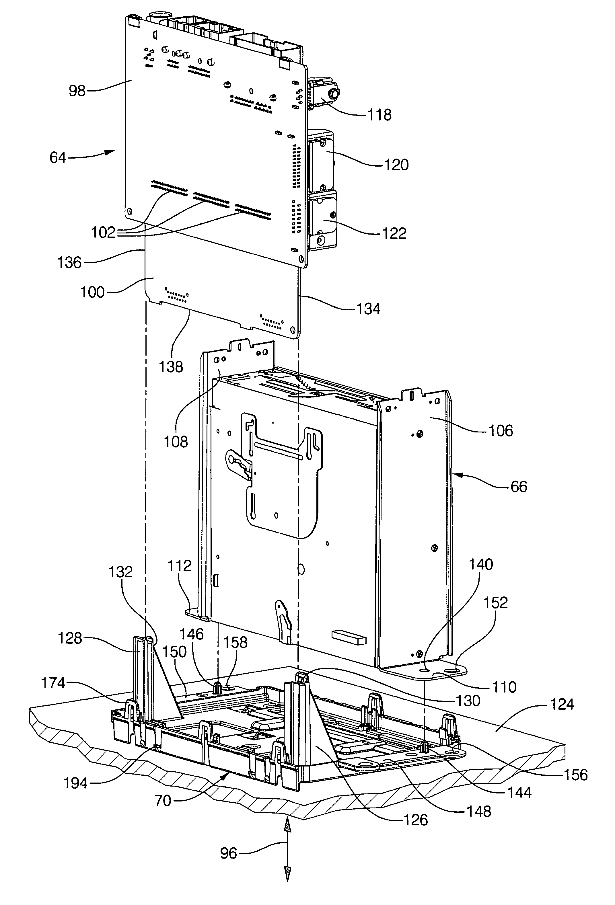
[0052]The present invention provides numerous product and process advantages which collectively result in substantial cost and labor savings. By way of example, the preferred design optimizes the assembly process. It minimizes the required handling of major components and subassemblies during the assembly cycle. Final assembly is optimized, wherein only seven major components and subassemblies are involved. This minimizes the number of work stations and fixtures, in-process transfers between work stations and total assembly cycle time. The inventive design permits selection of the optimal mechanical product configuration for a given receiver family. Furthermore, it permits idealized electrical and mechanical building block partitioning for common and unique elements.
[0053]The preferred embodiment of the invention contemplates screwless final assembly without the use of tools, fixtures and assembly machines. This greatly enhances in-process product flow in the factory, improves scheduling of final assembly, and allows labor intensive processes such as stick lead assembly to be largely moved off-line. This greatly reduces both direct and indirect labor requirements. Furthermore, inventory control is simplified inasmuch as position part proliferation is deferred to or near the end of process.

Problems solved by technology

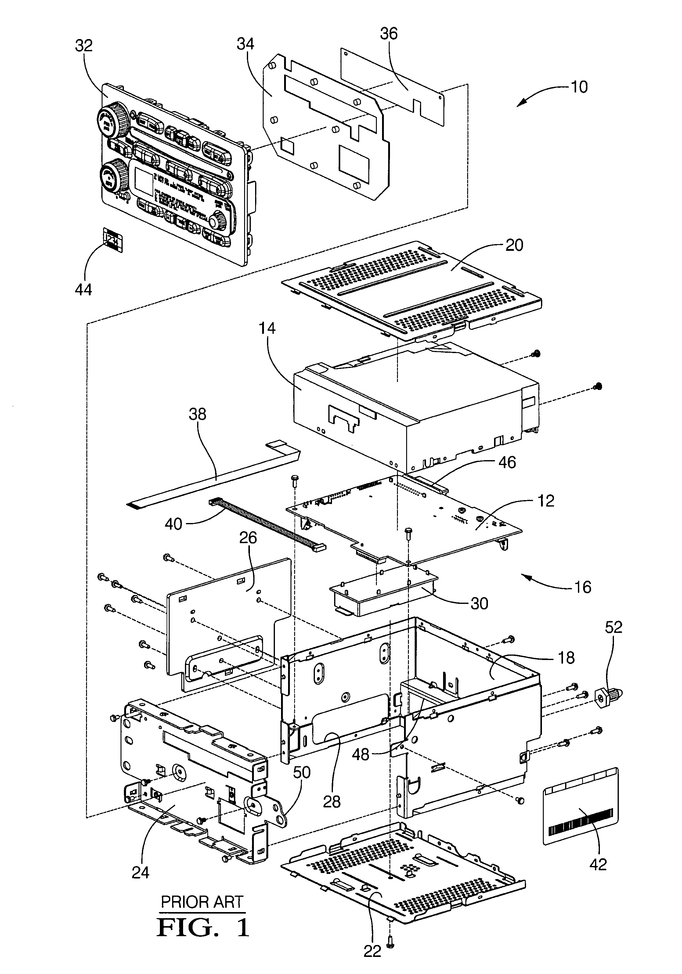
The use of such fasteners can have numerous drawbacks, particularly in a high volume production setting.
When threaded fasteners are used to assemble an electrical device, the assembly cycle time can be very long especially in high volume production.
Furthermore, using threaded fasteners presents a risk of any one of the following upstream failures occurring: stripping of fastener threads; insufficient torque resulting in an unseated fastener; excessive torque resulting in distension / deformation of the fastener or adjacent electrical components; installation of the wrong fastener type or size; foreign object damage due to fasteners and / or metal shavings dropping onto the assembly and / or subassembly; and stripping of the head of the threaded fastener.
Also, a fastener installation tool such as a driver and bit can slip off the fastener and impact an electrical component resulting in a damaged assembly.
If self-tapping fasteners are used, the process of driving the self-tapping fasteners into sheet metal often causes shavings of sheet metal to disperse into the assembly.
Such shavings have been known to cause electrical failures, such as shorts or corruption of magnetic components that can permanently damage the product.
Fasteners further require an additional inventory burden on the production line in that the production line must be continuously stocked with part numbers (fasteners) other than the integral components that add value to the assembly.
Such fixtures can be very complex, and the use of such fixtures usually requires extra handling of both the subassembly and of the resulting assembly thereby adding to the production cycle time and potentially compromising quality of the final product.
Unfortunately, with the density of the metal, the disadvantage of added weight is a side effect of the typical construction.
In a vehicle, added weight impacts fuel economy, as well as other hidden costs during assembly that can effect the cost of the product, like sharp edges of metal can be a potential hazard for assemblers in the manufacturing plant as well as added weight can limit the packaging of multiple parts in containers for inter and outer plant distribution.
For example, excessive temperatures can cause delicate electrical leads to fail or insulating materials to melt, thereby causing a short circuit resulting in damage to, or even failure of, the entire electrical device.
The use of such fasteners can have numerous drawbacks, particularly in a high volume production setting.
Or, a stripped or improper type of fastener may provide an insufficient clamping force.
Such fixturing can be very complex and use of such fixturing usually requires extra handling of both the component and of the resulting assembly, thereby adding to the production cycle time and potentially compromising quality of the final product.
When threaded fasteners are used, the assembly cycle time can be very long, especially in high volume production.
If self-tapping fasteners are used, the process of driving the self-tapping fasteners into metal often causes metal shavings to disperse into the assembly.
Such shavings have been known to cause electrical failures that can permanently damage the product.
Static electricity (electrostatics) is created when two objects having unbalanced charges touch one another, causing the unbalanced charge to transfer between the two objects.
If the object touched is an electronic device, such as a home stereo, home theatre system, computer, vehicle entertainment system or other electronic media system, this electrostatic discharge can be harmful to the sensitive electronic components of the device.
Similar problems may occur when using DVD and other magnetic media and disc players.
Accordingly, problems with the drainage of a static electric charge impacting sensitive electronic components continue to persist.
Unfortunately, each of the buttons has required individual fabrication and decoration, which significantly increases the total cost of an end product so designed.
Further, as the individual buttons are actuated, they can produce a squeaking noise due to the fact that each of the individual buttons includes a number of posts that mate with integrally formed guides in the housing.
Various automotive accessories, such as an automotive radio, also receive inputs from rocker switches, which, similar to button switches, have been painted and laser trimmed and also may create noise when a user actuates the rocker switch as the switch may engage a separate housing or trim plate.
Further, the increased temperature may place undesirable thermal stress on the display components.
Unfortunately, these systems require additional, cumbersome circuitry for turning the button light sources on and off.
However, because this location of the light pipe is typically shared by other electrical components and mechanical structures (i.e. button bodies, potentiometers, plastic ribs, LCD displays, etc.), the design of the light pipe may become complex, which may affect the efficiency of the lighting system.
Accordingly, a final design of the light pipe has often included complex structures that weave between the electrical components and mechanical structure.
Once light is provided to an entrance port of the light pipe, gradual changes in direction of light propagation by means of total internal reflection on non-parallel light pipe walls tend to introduce losses as collimation decreases.
Losses in collimation also increase the difficulty in directing light exiting the light pipe to the specific areas of the display panel.
The complexity of such light pipe designs makes computer simulation difficult and time consuming, which lends to prevention of design optimization by means of iterative prototyping and expensive design cycles drawn out with proof of concept often being delayed until injection molded light pipe prototypes can be produced.
In this regard, cost and durability factors can be significant in the final selection of the switch mechanisms to be utilized.
For example some of the switch mechanisms provide excess freedom of movement, have undesirable noise problems, are too expensive, have alignment problems in the socket or housing in which they are positioned, do not operate with the requisite tactile “feel”, or are simply too difficult to operate for the desired function.
The auxiliary jack allows playing the music, but does not necessarily allow for player control through the radio.
The problems with the glove box approach are the potential for damage to the device from other contents in the glove box, and the cable connection offers no flexibility for connecting to another device.
Damage may occur to the cable as well through normal use.
The auxiliary jack method allows more flexibility for devices, but limits the control and may incur damage through impact while a plug is connected.
Some aftermarket radios offer a USB (Universal Serial Buss) port on the front panel thereof, but may also incur damage due to the potential leverage on the face of the unit when a flash memory is connected, not to mention vehicle occupant impact issues resulting from braking and collisions.
Furthermore, connection interfaces open to the vehicle passenger compartment environment risk system damage from foreign objects and air-borne contamination, not to mention being aesthetically unattractive.
The rapidly changing customer market has initiated a drive to feature content on OEM (original equipment manufacturer) supplied radios for automobiles to provide those wants and that has an impact on interchangeability and potential safety issues.

Method used


Image

  • Lightweight audio system for automotive applications and method
  • Lightweight audio system for automotive applications and method
  • Lightweight audio system for automotive applications and method

Examples


Embodiment Construction

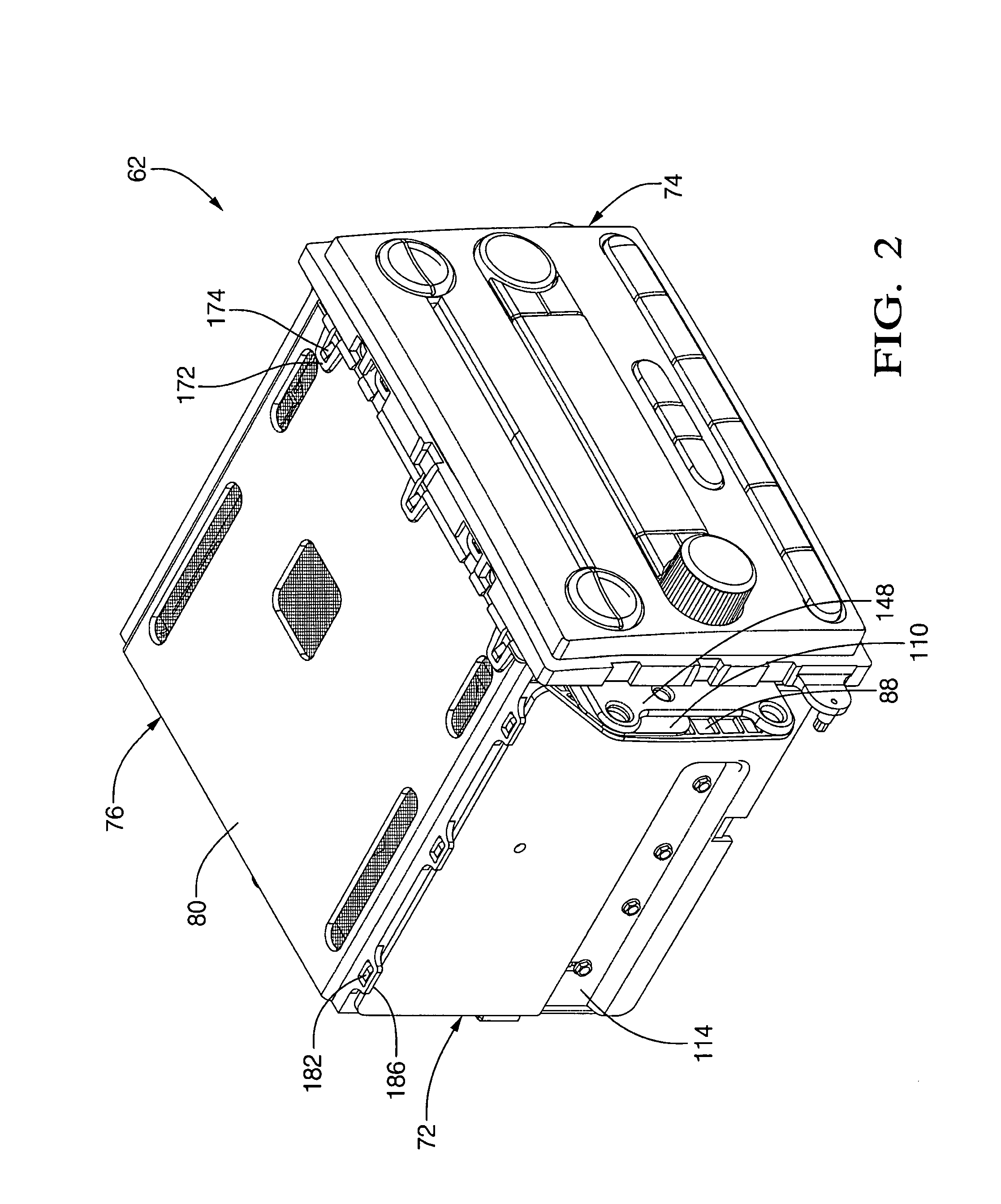
[0228]The present invention can be applied in its broadest sense to electronic devices and systems where shielding from radio frequency interference (RFI), electromagnetic interference (EMI), bulk current injection (BCI) and / or electrostatic discharge (ESD) is required. In addition to vehicle based radios and audio entertainment systems, the invention can be advantageously applied in “infotainment” and telematic systems. Furthermore, the present invention employs virtually “fastenerless” design architecture to facilitate low-cost, high volume production techniques.

[0229]A telematics product is a two-way communication / receiver system that enables access by a vehicle occupant to vehicle related information like geographic position / location through the use of a GPS module with antenna, vehicle diagnostics, crash sensors and air bag deployment. It also contains a phone module that is linked through a microphone in the vehicle and the radio speaker system for hands free calling via voice...


PUM

PropertyMeasurementUnit
temperatureaaaaaaaaaa
weightaaaaaaaaaa
angleaaaaaaaaaa

Abstract

A lightweight radio / CD player for vehicular application is virtually “fastenerless” and includes a case and frontal interface formed of polymer based material that is molded to provide details to accept audio devices such as playback mechanisms (if desired) and radio receivers, as well as the circuit boards required for electrical control and display. The case and frontal interface are of composite structure, including an insert molded electrically conductive wire mesh screen that has been pre-formed to contour with the molding operation. The wire mesh provides EMC, RFI, BCI and ESD shielding and grounding of the circuit boards via exposed wire mesh pads and adjacent ground clips. The PCB architecture is bifurcated into a first board carrying common circuit components in a surface mount configuration suitable for high volume production, and a second board carrying application specific circuit components in a wave soldered stick mount configuration. The major components and subassemblies are self-fixturing during the final assembly process, eliminating the need for dedicated tools, fixtures and assembly equipment. The major components and subassemblies self-interconnect by integral guide and connection features effecting “slide lock” and “snap lock” self-interconnection. The radio architecture includes improved push buttons employing 4-bar living hinge linkage and front loaded decorative trim buttons.

Description

RELATED APPLICATIONS[0001]The present application is related and claims priority to application U.S. Ser. No. 60 / 838,698 filed 18 Aug. 2006 to Chris R. Snider et al., entitled Lightweight Automotive Radio / CD Player and U.S. Ser. No. 60 / 931,467 filed 23 May 2007 to Chris R. Snider et al., entitled Lightweight Automotive Telematic Device, both assigned to a common assignee.TECHNICAL FIELD[0002]The present invention relates generally to apparatus for enclosing electrical subassemblies, and more specifically relates to apparatus for efficiently securing subassemblies to a chassis of an electrical assembly such as an automobile radio, compact disc playing mechanism, cassette tape playing mechanism, navigational aid, personal computer, personal and telematic communication devices or disk drive mechanism.BACKGROUND OF THE INVENTION[0003]Devices such as automobile radios or personal computers contain subassemblies such as cassette playing mechanisms or disk drives that are attached to the c...

Claims


Application Information

Patent Timeline
Patent Type & Authority Patents(United States)
IPC IPC(8): H05K5/00
CPCH04B1/082H05K7/20418H05K7/20436H05K9/0047H04R1/02H05K5/0226H05K9/0007H05K13/00H05K5/0217H05K7/20409B60R11/02G06F11/00B29C59/16H05K5/0221H05K1/0215Y10T29/49128H05K1/141H05K2201/09081H05K2201/10386H05K2201/10446Y10T428/24289Y10T29/5313Y10T16/547Y10T403/77Y10T16/5476Y10T74/20396Y10T29/49126Y10T29/49169Y10T29/49172Y10T29/4957Y10T29/49826Y10T29/49002Y10T29/49861Y10T29/49124Y10T29/4913Y10T403/70H05K9/0079H05K9/0081
Inventor SNIDER, CHRIS R.GUPTA, VINEETHUNTZINGER, JOSEPH K.COADY, MICHAEL G.STAPERT, CURTIS ALLENMEYER, KEVIN EARLGARNER, TIMOTHY D.BELL, JEFFREY T.VADAS, ROBERT L.MOESCHBERGER, DONALD G.OBERLIN, ALLEN E.BURTON, PAUL C.CARMAN, DAN D.STAHL, GARY L.MATLY, JOHN MICHAELHATCHER, RICK L.HASSLER, EDGAR GLENNNGUYEN, QUAN N.REED, WILLIAM R.PIEL, KIP R.WENDLING, JERRY J.KENWORTHY, TIM A.UGLUM, PAUL A.FYE, MICHAEL E.SCOTT, PHILIP M.
Owner APTIV TECH LTD
Why Eureka
Eureka Blog
Learn More