Photomask, focus measurement apparatus and focus measurement method
a focus measurement and focus measurement technology, applied in the field of photography masks, can solve the problems of inability to specify the focus variation with high precision, the difference in the focus position when the pattern of a product is exposed cannot be obtained, and the size of the resist pattern after development varies
- Summary
- Abstract
- Description
- Claims
- Application Information
AI Technical Summary
Benefits of technology
Problems solved by technology
Method used
Image


Examples
first embodiment
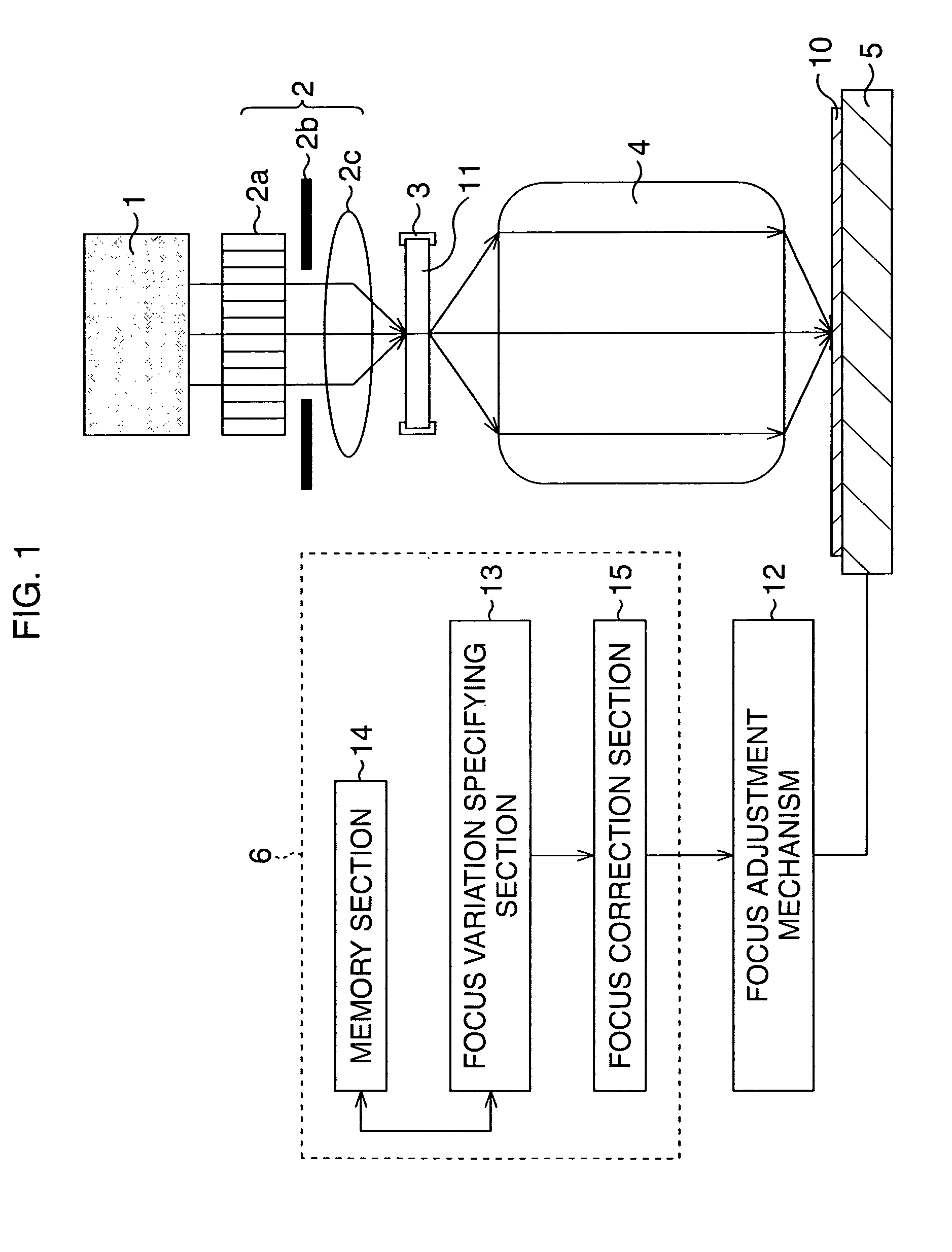
[0066]FIG. 1 is a schematic view showing an outline structure of an exposure system according to a first embodiment.
[0067]The exposure system performs a so-called reduced projection exposure and includes an illumination light source 1 irradiating exposure light, a condensing optical system 2 condensing the irradiated exposure light to a desired portion of a photomask, a reticle stage 3 to place and secure the photomask thereon, a projection optical system 4 projecting the exposure light passed through the mask pattern of the photomask to a desired portion of a transfer object, a wafer stage 5 to place and secure the transfer object thereon, and a focus control system 6 measuring and correcting focus variation of the exposure light on the transfer object.
[0068]The illumination light source 1 is, for example, an ArF excimer laser that irradiates ArF excimer laser light of a wave length of 193 nm as exposure light.
[0069]The condensing optical system 2 includes a fly-eye lens 2a, an ill...
modification example
[0094]Hereinafter, the description will be given of a modification example of the first embodiment. Here, for the same components and the like as of the first embodiment, the same numerical references will be used and detail description thereof will be omitted.
[0095]FIG. 7 is a schematic view showing an outline structure of an exposure system according to the modification example of the first embodiment.
[0096]The exposure system includes the illumination light source 1, the condensing optical system 2, the reticle stage 3, the projection optical system 4, and the wafer stage 5, as in the first embodiment, and further includes a focus control system 7 measuring and correcting the focus variation of exposure light in the transfer object.
[0097]The focus control system 7 is composed of a memory section 17 in which the data showing the relation between the size variation amount and the focus variation amount is stored and a difference value calculation section 18 to obtain size variation...
second embodiment
[0117]Next, the description will be given of a second embodiment. Here, for the same components and the like as of the first embodiment, the same numerical references will be used and detail description thereof will be omitted.
[0118]The present embodiment is to measure and correct the focus variation of the exposure light for the exposure system having the same structure as in the first embodiment, in which, however, the test photomask has a different structure. Here, plural (for example, two) pieces of test photomasks are used to perform multiple (double) exposures.
[0119]Along with increasing density in semiconductor elements, the microfabrication of the patterns formed by lithography is showing progress. As a method of forming a micropattern with high precision, a multiple exposure process using a Levenson type phase shift mask is proposed.
[0120]A method of the multiple exposure process will be described using FIGS. 11A to 11C.
[0121]For example, a case where the multiple exposure ...
PUM
| Property | Measurement | Unit |
|---|---|---|
| wave length | aaaaa | aaaaa |
| wave length | aaaaa | aaaaa |
| diameter | aaaaa | aaaaa |
Abstract
Description
Claims
Application Information
 - R&D
- Intellectual Property
- Life Sciences
- Materials
- Tech Scout
- Unparalleled Data Quality
- Higher Quality Content
- 60% Fewer Hallucinations
Browse by: Latest US Patents, China's latest patents, Technical Efficacy Thesaurus, Application Domain, Technology Topic, Popular Technical Reports.
© 2025 PatSnap. All rights reserved.Legal|Privacy policy|Modern Slavery Act Transparency Statement|Sitemap|About US| Contact US: help@patsnap.com