Friction stir welding method and method of manufacturing hollow body

a technology of friction stir welding and hollow body, which is applied in the direction of manufacturing tools, soldering devices, auxillary welding devices, etc., can solve the problems of deterioration in joining quality, increased apparatus cost, and troublesome associated setup work, so as to prevent the occurrence of defects in the joining end zone, the effect of variation in joining quality

Inactive Publication Date: 2010-05-25
SHOWA DENKO KK
View PDF5 Cites 5 Cited by
  • Summary
  • Abstract
  • Description
  • Claims
  • Application Information

AI Technical Summary

Benefits of technology

[0017]According to the method of any one of pars. 1) to 4), frictional heat generated during joining is removed as latent heat by the cooling medium which is held in place. Thus, in the case of time-consuming joining, joining of workpieces having high deformation resistance, joining of workpieces having a shape susceptible to accumulation of heat, etc., there can be restrained occurrence of a large temperature difference between a joining start zone and a joining end zone and occurrence of great variation in joining quality along the longitudinal direction of the joint portion. Also, since a significant temperature rise in the joining end zone is restrained, occurrence of defect in the joining end zone is prevented. Therefore, the entire joint can exhibit a predetermined joining strength, and appearance of a weld bead is consistent. Furthermore, merely holding the cooling medium along the overall length of a prospective joint region suffices, thereby eliminating need to employ the means for moving the cooling means and the control unit which are employed in the method disclosed in Patent Document 1, and thus lowering implementation cost. Additionally, since penetration of the cooling medium into an unjoined interface between workpieces is prevented, a deterioration in joining quality is restrained.
[0018]The method of par. 3) yields the following effects. In the case of a workpiece having a small thermal capacity, frictional-heat input causes a significant temperature rise. Thus, a temperature difference becomes significantly large between a joining start zone and a joining end zone; accordingly, a great variation arises in joining quality along the longitudinal direction of the joint portion, and a defect is apt to arise in the joining end zone, where temperature rises greatly. However, occurrence of these problems is prevented by means of holding the cooling medium on a surface of the workpiece having a smaller thermal capacity.
[0019]The method of par. 4) yields the following effects. In the case of a workpiece having a high high-temperature deformation resistance, the quantity of frictional heat generated during joining is large, causing a significant temperature rise. Thus, a temperature difference becomes significantly large between a joining start zone and a joining end zone; accordingly, a great variation arises in joining quality along the longitudinal direction of the joint portion, and a defect is apt to arise in the joining end zone, where temperature rises greatly. However, occurrence of these problems is prevented by means of holding the cooling medium on a surface of the workpiece having a high high-temperature deformation resistance.
[0020]The method of par. 5) allows the cooling medium to be held on a workpiece in a relatively easy manner.
[0021]The method of par. 6) eliminates a need to form the holder portion for every workpiece and enables application to a large number of workpieces.
[0022]According to the method of par. 7), frictional heat generated during joining is removed as latent heat by the cooling medium held on the cover. Thus, in the case of time-consuming joining, joining of a base and a cover which are made of a material having a high deformation resistance, etc., there can be restrained occurrence of a large temperature difference between a joining start zone and a joining end zone and occurrence of great variation in joining quality along the longitudinal direction of the joint portion. Also, since a significant temperature rise in the joining end zone is restrained, occurrence of defect in the joining end zone is prevented. Therefore, in a manufactured hollow body, the entire joint portion between the cover and the base can exhibit a predetermined joining strength, and appearance of a weld bead is consistent. Furthermore, merely holding the cooling medium on the cover suffices, thereby eliminating need to employ the means for moving the cooling means and the control unit which are employed in the method disclosed in Patent Document 1, and thus lowering implementation cost. Additionally, since penetration of the cooling medium into an unjoined interface between the cover and the base is prevented, a deterioration in joining quality is restrained.

Problems solved by technology

Also, due to occurrence of a blowhole defect or hot cracking, there arises a problem of deterioration in joining quality.
However, since electron beam welding must be carried out within a vacuum, apparatus cost increases.
Thus, associated setup work is rather troublesome.
Also, since consumables, such as filler metal and shield gas, are not used, implementation cost is low.
However, even in the friction stir welding method, in the case of a long joint, a deep joint, workpieces having high deformation resistance, etc., the amount of frictional heat generated during joining is significantly large.
Accordingly, in the case of time-consuming joining, joining of workpieces having high deformation resistance, joining of workpieces having a shape susceptible to accumulation of heat, etc., a temperature difference becomes large between a joining start zone and a joining end zone, thereby raising a problem of great variation in joining quality along the longitudinal direction of the joint portion.
However, according to the method disclosed in Patent Document 1, the cooling means must be moved synchronously with the friction-stir-welding tool, and the spraying rate of the cooling medium from the cooling means must be controlled by the control unit, thus involving a problem of an increase in cost of apparatus for carrying out the method.
Therefore, joining quality may deteriorate.

Method used


Image

  • Friction stir welding method and method of manufacturing hollow body
  • Friction stir welding method and method of manufacturing hollow body
  • Friction stir welding method and method of manufacturing hollow body

Examples


embodiment 1

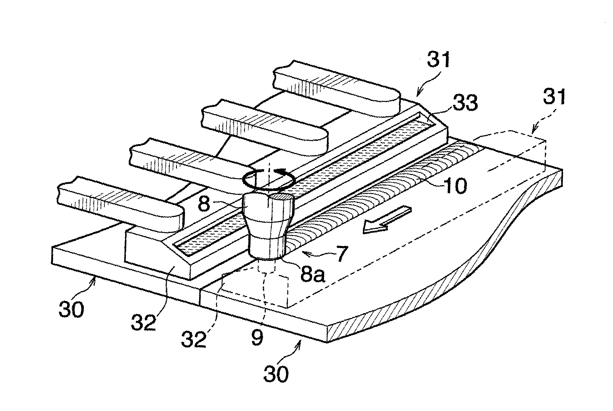
[0032]The present embodiment is shown in FIGS. 1 to 3 and is a method of manufacturing a hollow body which consists of a base having a recess, and a cover fitted into the recess and closing the opening of the recess.

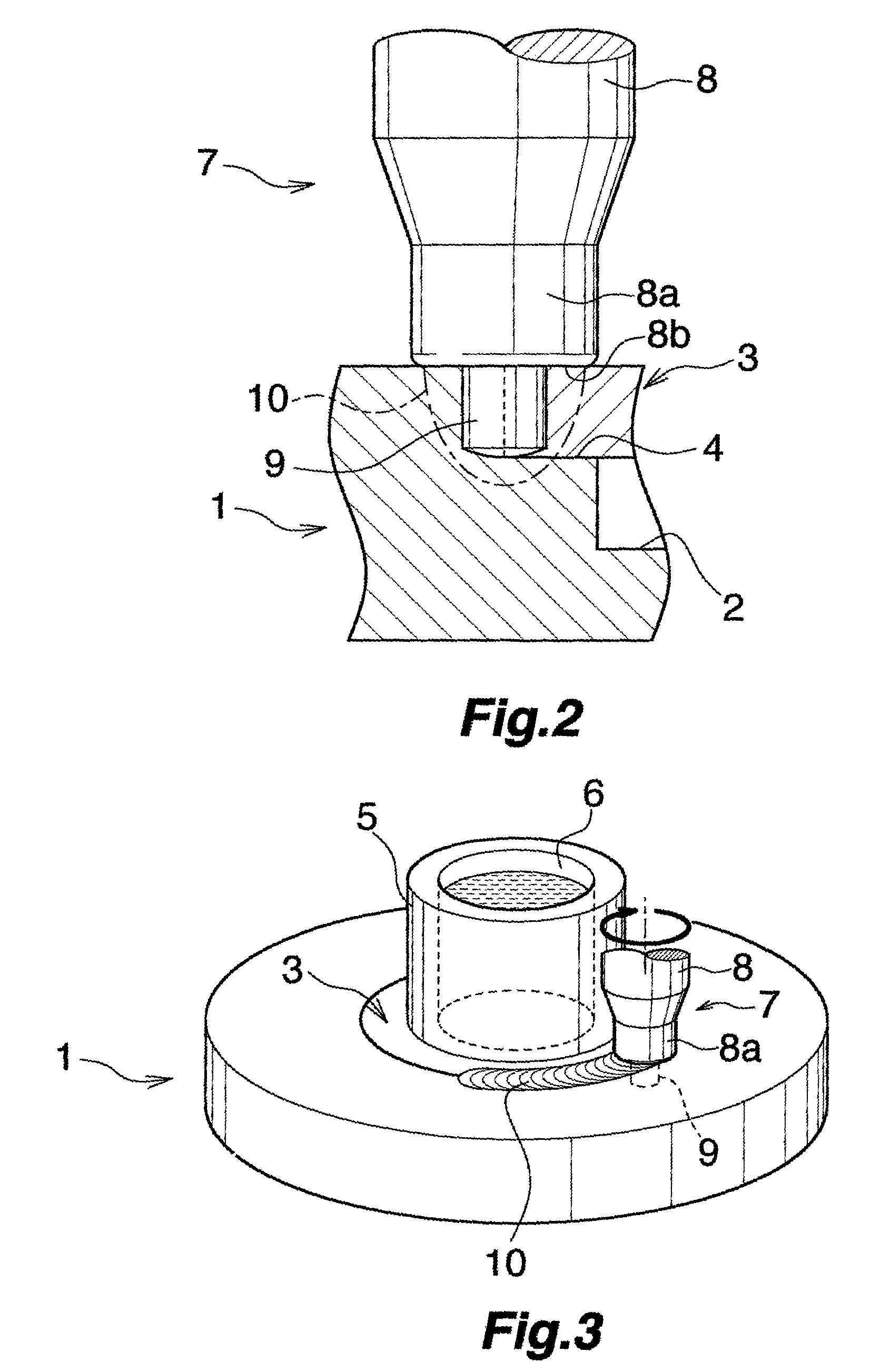
[0033]First, there are prepared a base 1 having a recess 2 whose inner peripheral surface is circular, and a disklike cover 3 which is fitted into the recess 2 and adapted to close the opening of the recess 2. A stepped portion 4 for supporting a circumferential portion of the cover 3 is formed on the inner circumferential surface of the recess 2 of the base 1 at a portion located on a side toward a bottom. The thickness of the cover 3 is smaller than the overall depth of the recess 2 and is equal to the depth of a portion of the recess 2 located above the stepped portion 4. The diameter of the cover 3 is equal to or slightly smaller than the inside diameter of the recess 2 as measured above the stepped portion 4. A cylindrical cooling-medium holder portion 5 whose inter...

experimental example

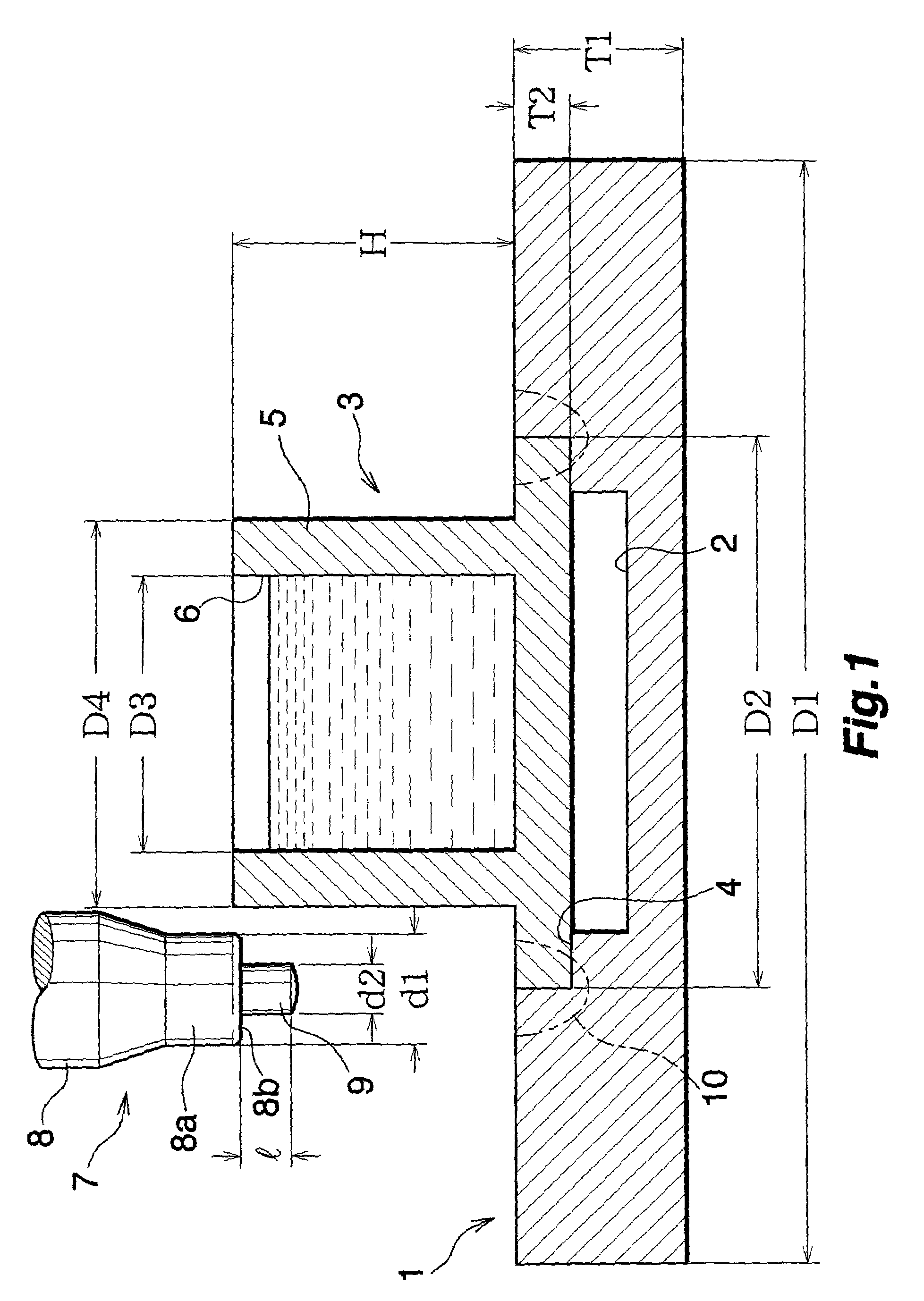
[0045]The base 1 and the cover 3 formed from JIS A2014-T6 were prepared. Outside diameter D1 of base 1: 200 mm; thickness T1 of base 1: 30 mm; inside diameter D2 of recess 2 as measured above stepped portion 4 (=diameter of cover 3): 100 mm; thickness T2 of cover 3 (=depth of recess 2 as measured above stepped portion 4): 10 mm; height H of holder portion 5: 50 mm; inside diameter D3 of holder portion 5: 50 mm; and outside diameter D4 of holder portion 5: 70 mm.

[0046]The prepared friction-stir-welding tool 7 had the following dimensions. Diameter d1 of shoulder portion 8b as measured at end face of small-diameter portion 8a of rotor 8: 20 mm; diameter d2 of probe 9: 9 mm; and length l of probe 9: 10 mm.

[0047]Water of room temperature was placed to a depth of 30 mm in the cooling-medium accommodation recess 6 of the holder portion 5. Friction stir welding was carried out 360 degrees along the prospective joint region, with the probe rotational speed set to 500 rpm and the probe advan...

embodiment 2

[0052]The present embodiment is shown in FIG. 4 and is a method of manufacturing a hollow body which consists of a base having a recess, and a cover fitted into the recess and closing the opening of the recess.

[0053]In Embodiment 2, the holder portion 5 is not formed on the upper surface of the cover 3. When friction stir welding is to be performed, the base 1 is placed on a turntable 20, and the base 1 is fixed on the turntable 20 by means of a plurality of base clamp members 21 provided on the turntable 20. Furthermore, the cover 3 is fixed on the base 1 by means of a cover clamp member 22 provided separately from the turntable 20.

[0054]The cover clamp member 22 has a holder portion 23, which, in turn, has a closed-bottomed cooling-medium accommodation recess 24. In a state in which a liquid-phase cooling medium is placed in the cooling-medium accommodation recess 24 of the holder portion 23, the base 1 and the cover 3 undergo friction stir welding in a manner similar to that of E...


PUM

PropertyMeasurementUnit
diameter D1aaaaaaaaaa
diameteraaaaaaaaaa
diameter D3aaaaaaaaaa

Abstract

A friction stir welding method in which a base having a recess, and a cover for fitting into and closing the opening of the recess are prepared. A stepped portion on the inner circumferential surface of the recess at an intermediate depth allows a peripheral portion of the cover to rest thereon. A cylindrical holder portion having a cooling-medium accommodation recess is formed integrally with the outer surface of the cover. The cover is fitted into the recess and placed on the stepped portion. A cooling medium is placed in the cooling-medium accommodation recess. A friction-stir-welding tool probe is plunged into a peripheral portion of the base around an opening of the recess and into a peripheral portion of the cover. During rotation of the probe, the base, and the cover, and the probe undergo relative movement, friction-stir-welding the base and the cover together.

Description

TECHNICAL FIELD[0001]The present invention relates to a friction stir welding method for manufacturing metal products to be utilized in various industries, as well as to a method of manufacturing a hollow body.BACKGROUND ART[0002]The friction stir welding method is a solid-phase joining method, and thus has an advantage that deformation or cracking caused by thermal strain is less likely to arise as compared with an arc welding process, such as TIG or MIG. Also, when the arc welding process is employed for joining workpieces of a light metal, such as aluminum, in such a manner as to have a weld penetration depth of 5 mm or greater, multi-layer welding is required. Thus, the number of steps increases. Also, due to occurrence of a blowhole defect or hot cracking, there arises a problem of deterioration in joining quality. Meanwhile, even in the case of a weld penetration depth of 5 mm or greater, an electron beam welding process can achieve joining by a single pass. However, since ele...

Claims


Application Information

Patent Timeline
Patent Type & Authority Patents(United States)
IPC IPC(8): B23K20/12
CPCB23K20/1235B23K20/126B23K20/1245B23K2203/10B23K2103/10
Inventor NAGANO, YOSHITAKA
Owner SHOWA DENKO KK
Why Eureka
Try Eureka