
Selective copper-silicon-nitride layer formation for an improved dielectric film/copper line interface

a technology of copper-silicon-nitride and dielectric film, which is applied in the direction of liquid surface applicators, pretreated surfaces, coatings, etc., can solve the problems of copper being undetectedly peeled during polishing, the tendency of silicon dioxide to diffuse into silicon dioxide, silicon and other adjacent dielectric materials, and the failure of integrated circuits, etc., to achieve the effect of improving the adherence to the underlying copper interconnect and reducing the dielectric constant (

Inactive Publication Date: 2010-05-18
APPLIED MATERIALS INC
View PDF5 Cites 11 Cited by
  • Summary
  • Abstract
  • Description
  • Claims
  • Application Information

AI Technical Summary

Benefits of technology

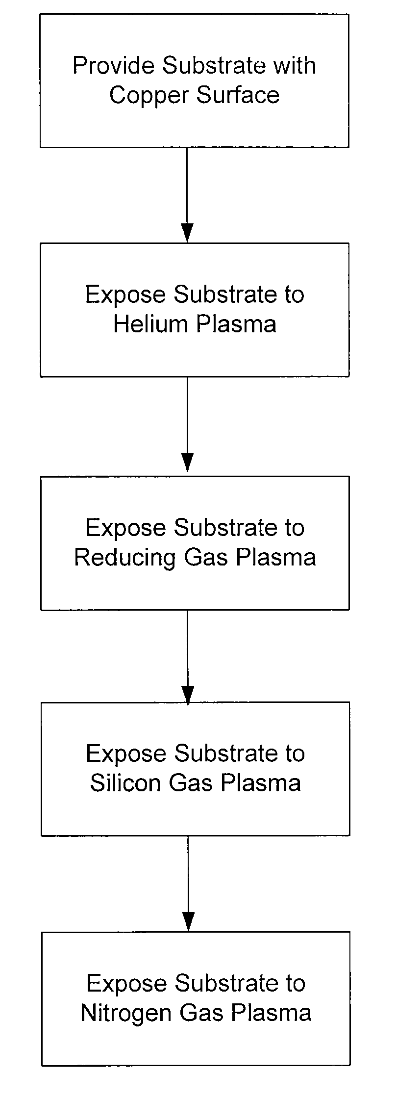
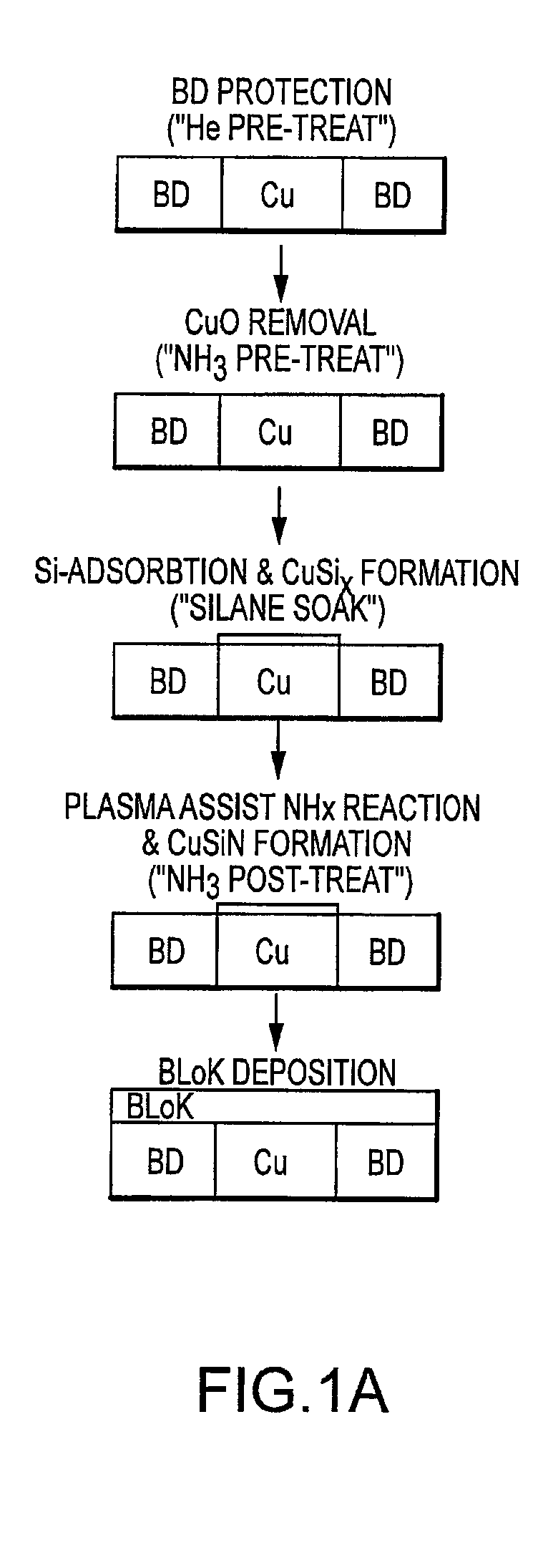
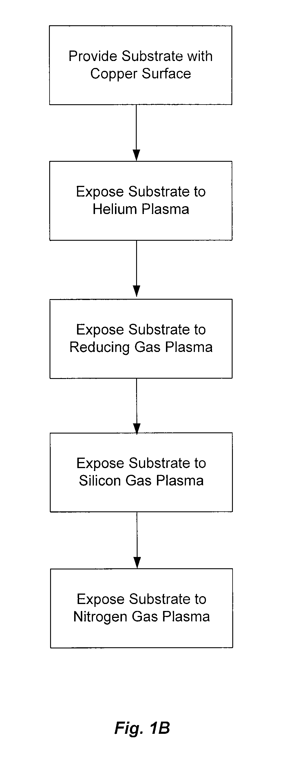
The patent describes a process for forming a layer of copper silicon nitride on a copper surface, which can serve as a barrier for copper interconnects in semiconductor devices. The process involves a series of plasma treatments using helium, reducing gas, silane, and ammonia and molecular nitrogen to selectively form copper silicide and copper silicon nitride layers, respectively. The resulting copper silicon nitride layer has improved adhesion to the copper surface and can be used to deposit a dielectric barrier for copper interconnects. The process can be carried out without significantly changing the copper's sheet resistance or the dielectric constant of the surrounding materials.

Problems solved by technology

One problem with the use of copper in the interconnect structures is its tendency to diffuse into silicon dioxide, silicon and other adjacent dielectric materials.
Poor adhesion of the copper to a diffusion barrier results in portions of the copper being undesirably peeled away during polishing.
This condition can also render an integrated circuit defective.

Method used


Image

  • Selective copper-silicon-nitride layer formation for an improved dielectric film/copper line interface
  • Selective copper-silicon-nitride layer formation for an improved dielectric film/copper line interface
  • Selective copper-silicon-nitride layer formation for an improved dielectric film/copper line interface

Examples


Embodiment Construction

[0026]With the advent of copper dual damascene, dielectric copper barriers are becoming the cornerstone for back end of line device reliability. The interface between copper and dielectric barrier is often the fastest diffusion path for the EM of copper, and that the improved adhesion of barrier film to copper increases the lifetime of EM. The present invention includes processes for engineering an interface between copper and a barrier layer to improve the EM performance. These processes can improve EM performance up to an order of magnitude or more compared to conventional barrier layer deposition by forming a thin (˜100 Å or less) CuSixNy adhesion layer between the copper film and barrier layer.

[0027]The present processes for forming the CuSixNy barrier layer can achieve the following results: (1) a small change in the dielectric constant (κ) of the nearby dielectric material; (2) a small increase in the sheet resistance (Rs) of the copper film; (3) a long EM lifetime; and (4) a ...


PUM

PropertyMeasurementUnit
temperatureaaaaaaaaaa
dielectric constantsaaaaaaaaaa
dielectric constantaaaaaaaaaa

Abstract

A process to form a copper-silicon-nitride layer on a copper surface on a semiconductor wafer is described. The process may include the step of exposing the wafer to a first plasma made from helium. The process may also include exposing the wafer to a second plasma made from a reducing gas, where the second plasma removes copper oxide from the copper surface, and exposing the wafer to silane, where the silane reacts with the copper surface to selectively form copper silicide. The process may further include exposing the wafer to a third plasma made from ammonia and molecular nitrogen to form the copper silicon nitride layer.

Description

CROSS-REFERENCES TO RELATED APPLICATIONS[0001]This application claims the benefit of U.S. Provisional Application No. 60 / 868,861, filed Dec. 6, 2006. The entire contents of the provisional application is herein incorporated by reference for all purposes.BACKGROUND OF THE INVENTION[0002]Integrated circuits (IC) are manufactured by forming discrete semiconductor devices on a surface of a semiconductor substrate, such as a silicon (Si) wafer. A multi-level network of interconnect structures is then formed to interconnect the devices. Copper (Cu) is the wiring material of choice for interconnect structures of advanced IC devices having a high circuit density. In addition to superior electrical conductivity, copper is more resistant than aluminum (Al) to electromigration, a phenomenon that may destroy a thin film conductive line during IC operation.[0003]In the semiconductor industry, much effort is spent in developing smaller IC devices with ever-increasing operating speeds. To increase...

Claims


Application Information

Patent Timeline
Patent Type & Authority Patents(United States)
IPC IPC(8): H01L21/469
CPCH01L21/76826H01L21/76849H01L21/76867H01L21/76864H01L21/76856
Inventor LEE, SANG M.ZUBKOV, VLADIMIRCUI, ZHENIJIANGSHEK, MEIYEEXIA, LI-QUNM'SAAD, HICHEM
Owner APPLIED MATERIALS INC
Learn More