
Apparatus and method for ion beam implantation using ribbon and spot beams

a technology of ion beam and apparatus, which is applied in the field of apparatus for ion beam implantation using ribbon and spot beam, can solve the problems of ensuring a ribbon beam and detectable stripes of varying ion beam dose in the workpi

Active Publication Date: 2010-03-09
ADVANCED ION BEAM TECHNOLOGY INC
View PDF14 Cites 4 Cited by
  • Summary
  • Abstract
  • Description
  • Claims
  • Application Information

AI Technical Summary

Benefits of technology

The present invention relates to an ion implantation apparatus for semiconductor wafers and flat panels. The apparatus includes an ion source, extraction assembly, mass analyzer magnet, and beam density controller. The ion beam has a relatively tall and narrow cross-section in the non-dispersive plane of the magnet. The apparatus also includes a Faraday beam current measurement device for scanning the beam to measure its uniformity. The invention provides a single dipole magnet for mass-analytical magnetization of the ion beam, which allows for better control of the beam's uniformity. The apparatus also includes a first lens for shaping the beam and a second lens for collimating the beam. Additionally, the invention provides optional means of deceleration and acceleration of the ion beam for filtering out contaminants and improving the beam's uniformity.

Problems solved by technology

In certain circumstances such as when using high-current low energy beams it may not be possible to assure a ribbon beam that is sufficiently uniform.
The currents in the multipole lens in either mode may be adjusted to fine-tune the beam current density profile of the beam, even though at low energy this control is insufficient to ensure a uniform implant in one pass with a ribbon beam.
Without a smooth beam profile, the method of passing the workpiece in regular increments through the ion beam may cause detectable stripes of varying ion beam dose in the workpiece.

Method used


Image

  • Apparatus and method for ion beam implantation using ribbon and spot beams
  • Apparatus and method for ion beam implantation using ribbon and spot beams
  • Apparatus and method for ion beam implantation using ribbon and spot beams

Examples


first embodiment

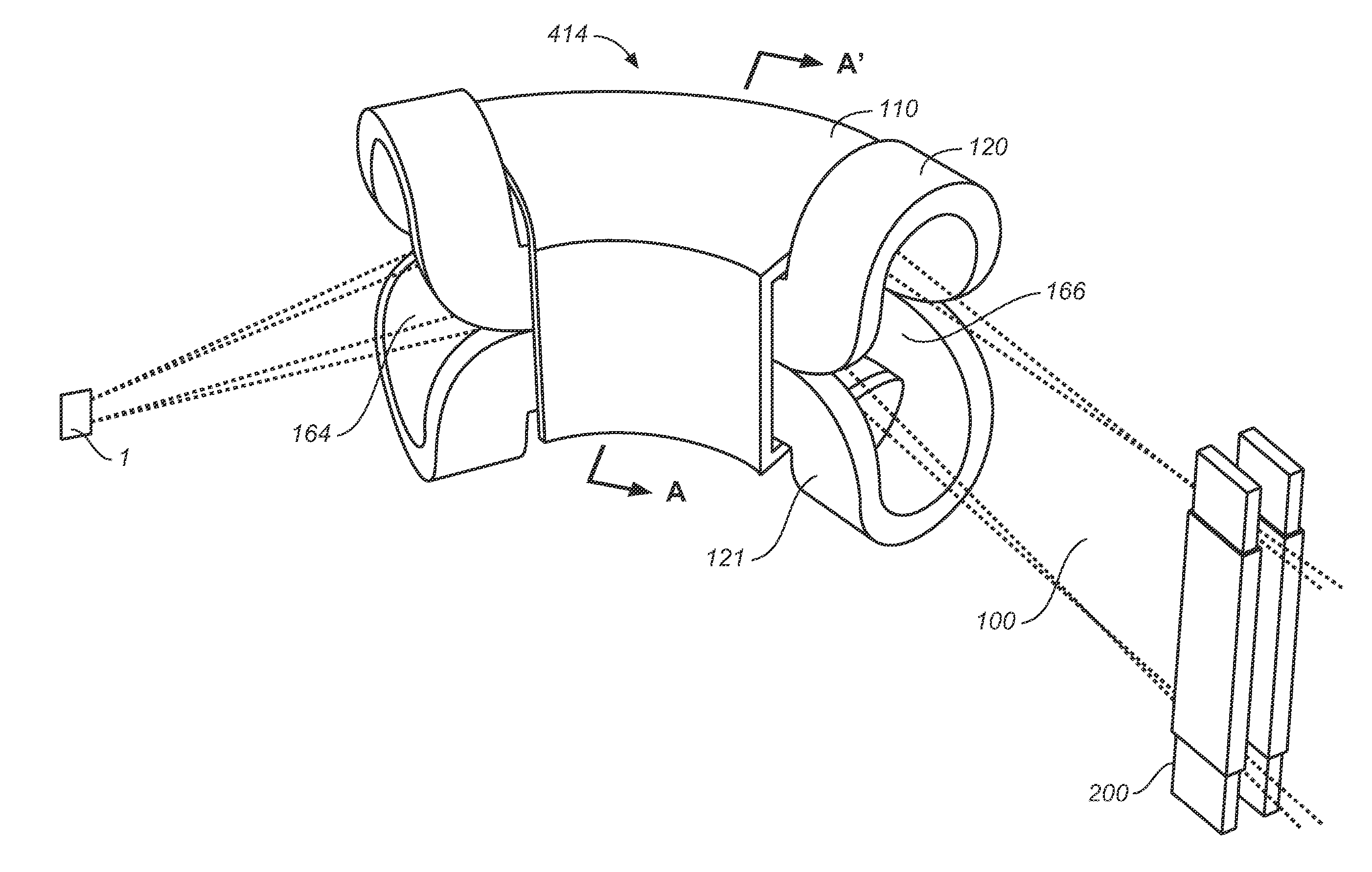
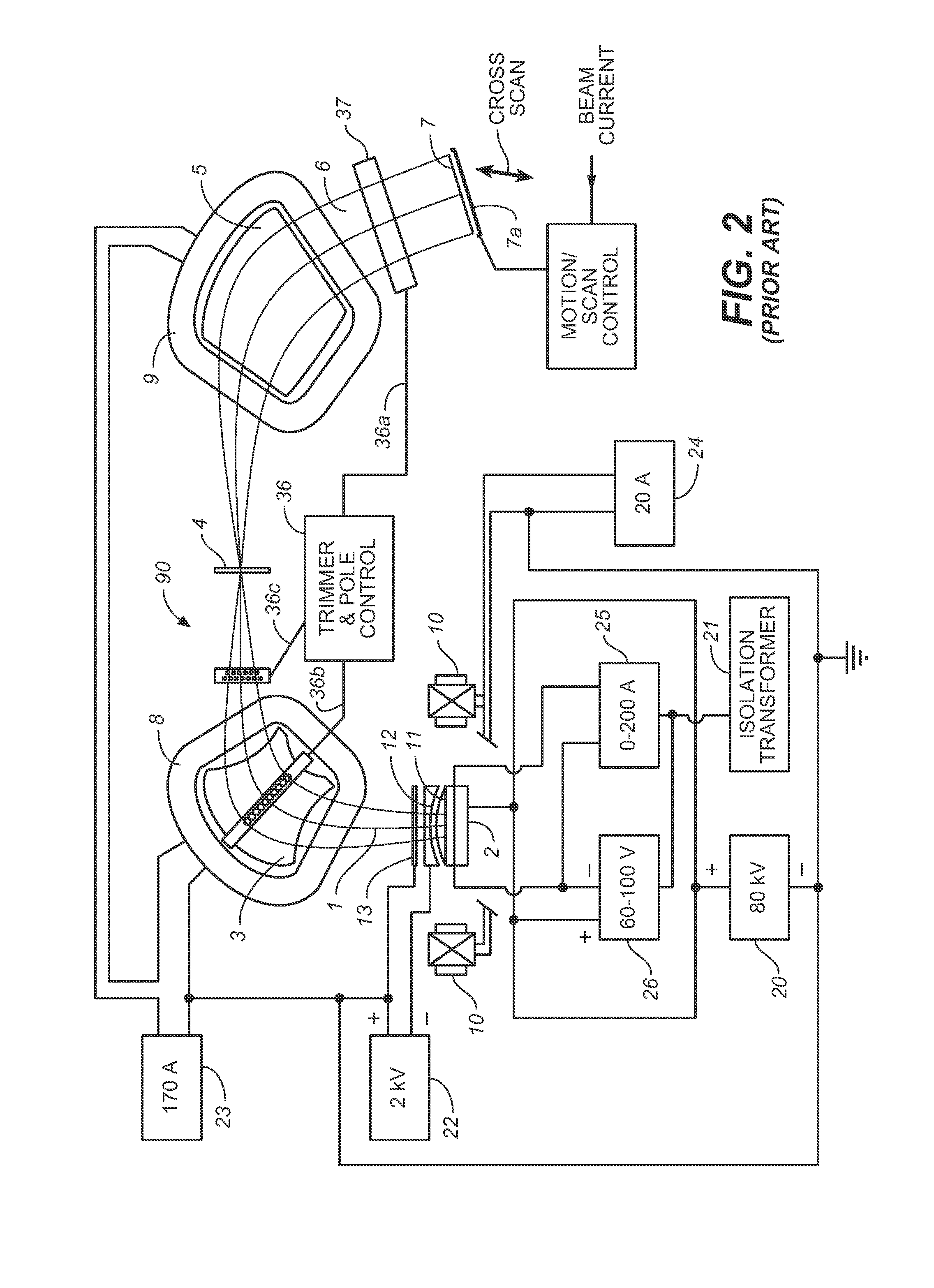
[0041]FIG. 3 is a perspective view of an ion implantation system of the present invention. The system comprises an ion source 102 that produces an ion beam 100 that emanates from a divergent extraction optics similar to those shown in FIG. 2, a mass analyzer magnet 414, and a collimator lens 200 As will be appreciated by those skilled in the art, these elements are housed in a vacuum enclosure (not shown). Magnet 414 comprises upper and lower coils 120, 121 and a yoke 110 with an entrance aperture 164 and an exit aperture 166. The magnet is curved over an arc of about 90°. The cross-section of the ion beam is relatively tall and thin and the longer dimension of the cross-section lies in the non-dispersive plane of magnet 444. The ion beam is slightly divergent upon exiting the extraction electrode; and as the beam travels along the beam path, it continues to become taller as the beam rays continue to diverge such that when it approaches the target (which may be a semiconductor wafer...

second embodiment

[0042]The analyzer magnet in FIG. 3 has a central passageway for the beam that has a top and bottom that are parallel from entrance aperture 164 to exit aperture 166. Thus, a cross-section of the magnet taken along lines A-A′ of FIG. 3 at any point along the radius of curvature of the magnet is the same. However the ion beam is diverging. In a second embodiment, the construction of the magnet is modified as illustrated by the three cross sections in FIGS. 4a, b, and c so that the height of the beam passage through the magnet increases as the beam expands. In particular, as shown in FIG. 4a, which depicts a cross-section closest to the entrance aperture 164 of the magnet, the height of the central passageway 160 is smallest. As shown in FIG. 4c, which depicts a cross-section closest to the exit aperture 166, the height of the central passageway is largest; and as shown in FIG. 4b which depicts a cross-section between those of FIGS. 4a and 4c, the height is intermediate that of the ot...


PUM


Abstract

An ion implantation apparatus with multiple operating modes is disclosed. The ion implantation apparatus has an ion source and an ion extraction means for extracting a ribbon-shaped ion beam therefrom. The ion implantation apparatus includes a magnetic analyzer for selecting ions with specific mass-to-charge ratio to pass through a mass slit to project onto a substrate. Multipole lenses are provided to control beam uniformity and collimation. A two-path beamline in which a second path incorporates a deceleration or acceleration system incorporating energy filtering is disclosed. Finally, methods of ion implantation are disclosed in which the mode of implantation may be switched from one-dimensional scanning of the target to two-dimensional scanning.

Description

CROSS REFERENCE TO RELATED APPLICATIONS[0001]Under 35 U.S.C. 120, this application claims priority to U.S. Provisional Application 60 / 813,301 entitled “Apparatus and Methods for Ion Beam Implantation using Ribbon and Spot Beams,” dated Jun. 12, 2006, and is related to U.S. patent application Ser. No. 11 / 209,484, entitled “Apparatus and Methods for Ion Beam Implantation,” filed Aug. 22, 2005, and U.S. patent application Ser. No. 11 / 209,476 entitled “Apparatus and Methods for Ion Beam Implantation Using Ribbon and Spot Beams,” now U.S. Pat. No. 7,326,941, issued Feb. 5, 2008, all of which is incorporated herein by reference.FIELD OF THE INVENTION[0002]The invention disclosed herein relates generally to apparatus for performing ion implantation. Specifically, this invention relates to an improved implantation apparatus and methods for performing a high / medium current ion implantation at different ion energies.BACKGROUND OF THE INVENTION[0003]Ion implantation is a ballistic process used...

Claims


Application Information

Patent Timeline
Patent Type & Authority Patents(United States)
IPC IPC(8): H01J37/317H01J37/28
CPCH01J37/05H01J37/08H01J37/1472H01J37/3171H01J2237/04756H01J2237/057H01J2237/083H01J2237/1503H01J2237/201H01J2237/20221H01J2237/30472H01J2237/31701
Inventor CHEN, JIONG
Owner ADVANCED ION BEAM TECHNOLOGY INC
Learn More