
Apparatus for irradiating liquids

a liquid-irradiation apparatus and liquid-irradiation technology, applied in chemical/physical/physical-chemical stationary reactors, chemical/physical/physical-chemical processes, energy-based chemical/physical/physical-chemical processes, etc., can solve the problem of infeasible large reactors, exponential decrease in the radiation intensity of the medium to be treated, and unfavorable residence time behaviour, etc. problem, to achieve the effect of improving the cross-transmission

Inactive Publication Date: 2010-01-26
BAYER AG
View PDF25 Cites 23 Cited by
  • Summary
  • Abstract
  • Description
  • Claims
  • Application Information

AI Technical Summary

Benefits of technology

[0013]The apparatus (reactor) for radiating UV light into liquids is distinguished, because of its optimal and uniform mixing behaviour, by improved mass transfer, thereby ensuring reliable and effective sterilization. The apparatus is readily integrated into existing plants and is easy to clean. Another advantage is the compact design of the apparatus.DETAILED DESCRIPTION
[0014]The apparatus is characterized in that specific flow conditions are generated, in an annular-gap duct transparent to UV light, which cause intensive mass transfer over the entire length of the duct. The apparatus comprises e.g. a UV radiation source, which can be encompassed by a quartz field tube (emitter jacket tube), and a product duct (irradiation chamber) which is transparent to UV light and is perfused by the reaction medium. The particular characteristic of the irradiation chamber is intensive, uniform cross-mixing prevailing over the entire length and perpendicular to the principal direction of the product flow, and a residence time distribution constrained by turbulent product flow.
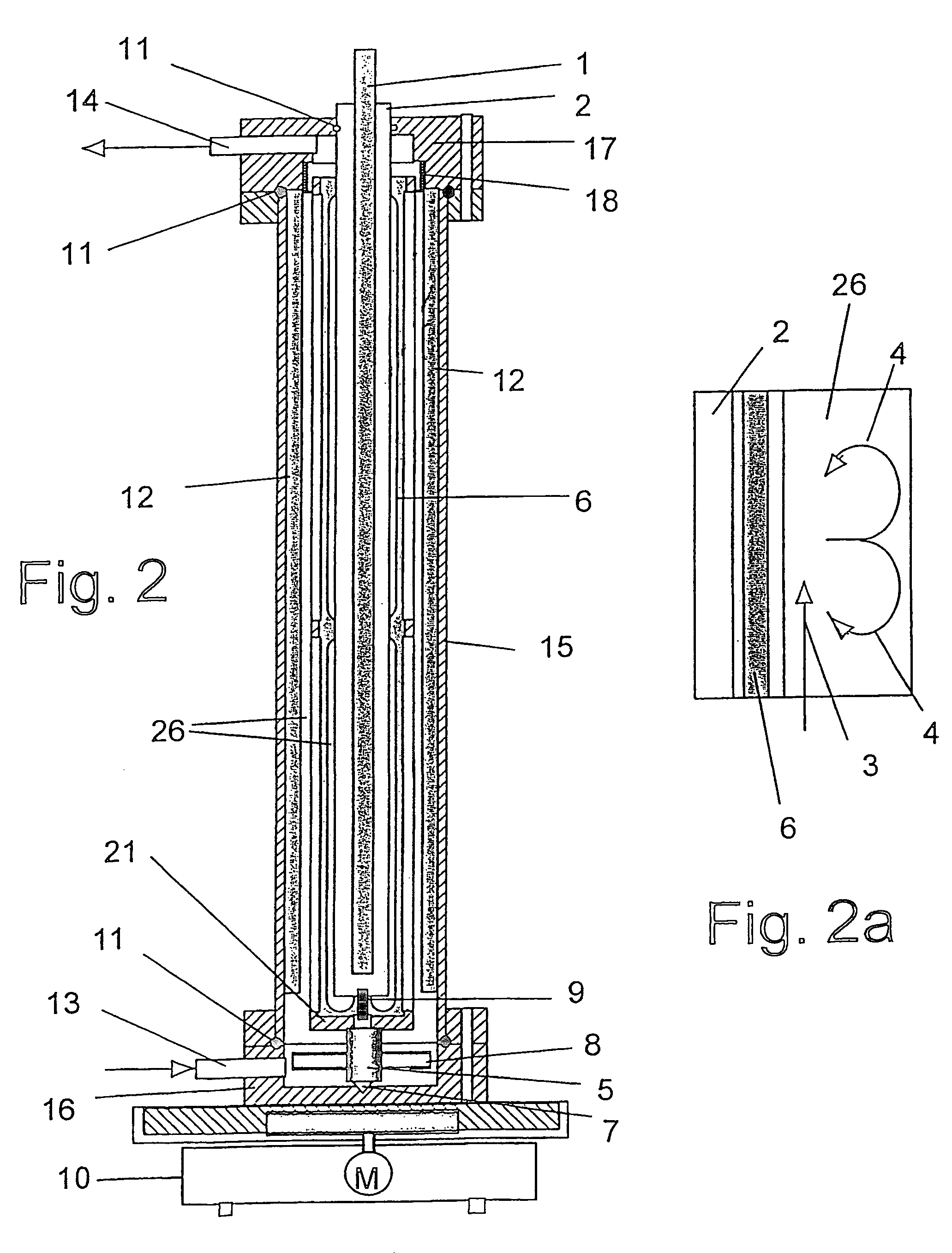
[0015]Said cross-mixing ensures that the liquid layers which are at a greater distance from the radiation source and which, particularly with strongly light-absorbing media, receive little or no UV radiation, enter into intensive transfer with the UV irradiated layers close to the radiation source. This is ensured e.g. by special flow routing in the apparatus, producing a multiplicity of successive quasi-cellular circulation flows. The requisite residence time of the products in the reactive duct layers is thus minimized, resulting in minimal damage to the products due to the radiation dose in conjunction with reliable sterilization or virus deactivation. The secondary flows are generated by agitation, upon flow round internals or upon flow through spiral ducts.
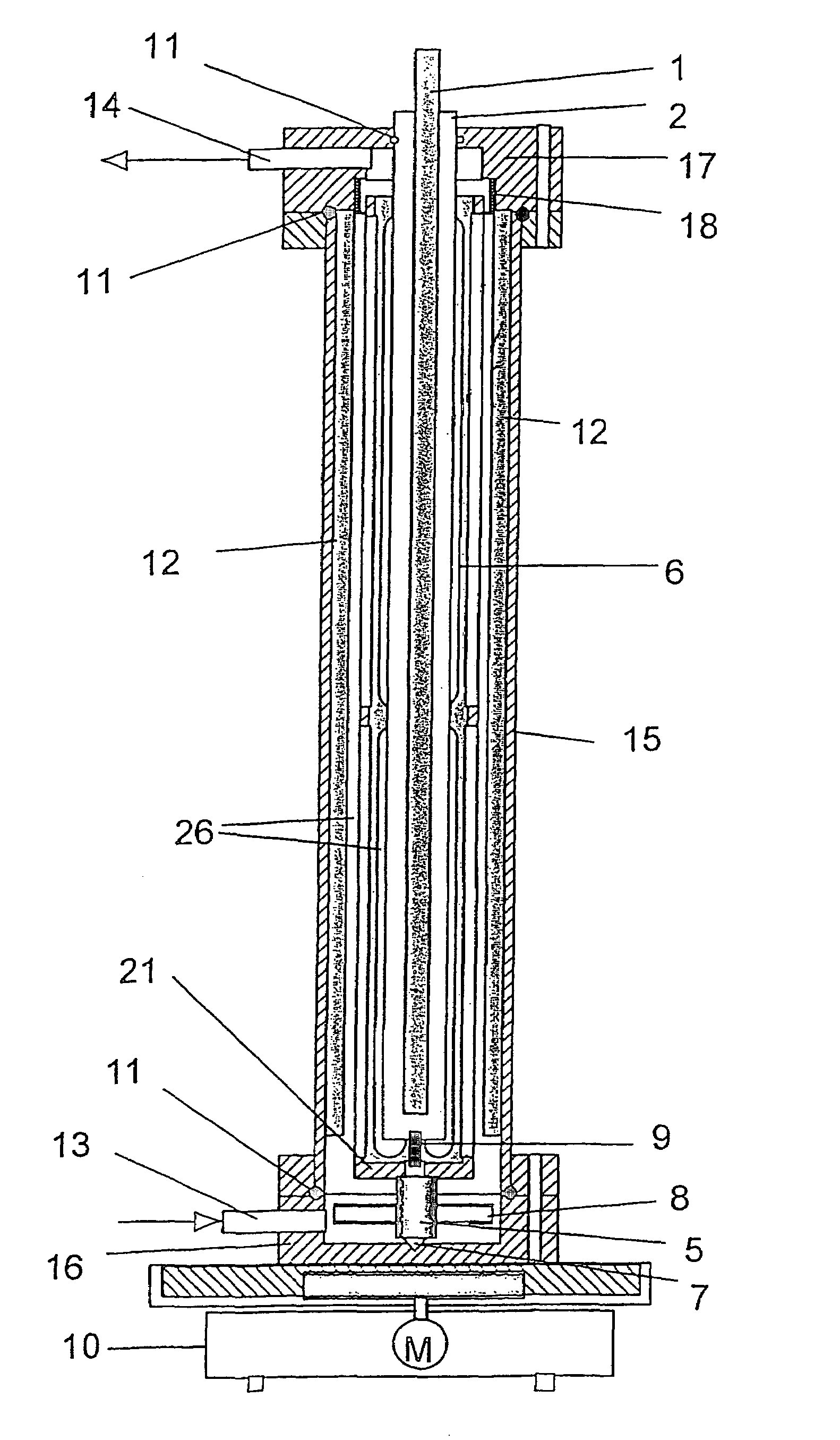
[0023]CFD studies have shown, surprisingly, that the optional fitting of additional baffles on the outer cylinder periphery, which cause tangential flow to be attenuated in favour of radial flows for the purpose of further improvement in the cross transfer, does not adversely effect the residence time behaviour. The stirrer is driven via an external motor with a slide ring-sealed stirrer shaft or preferably packinglessly by means of an electromagnetically coupled drive mechanism or an impeller driven by the incoming product stream. Mechanically intensified cleaning of the reactors can take place in a simple manner in the closed state with the stirrer drive mechanism switched on, or by brushing after the inner glass cylinder has been removed.

Problems solved by technology

Problems in the use of reactors for radiating ultraviolet light into liquid reaction media are caused by the fact that the radiation intensity in the medium to be treated decreases exponentially with increasing distance from the radiation source.
The thin-film reactors currently in use can be scaled up only with difficulty to industrial scales, as the only way to keep the film thickness constant in the scale-up is to increase the diameter in proportion with the throughput, which on an industrial scale results in infeasibly large reactors.
A further negative factor is the unfavourable residence time behaviour of the liquid films, which given the generally low penetration depth of the UV radiation to the reaction medium are necessarily very thin and consequently exhibit laminar flow, in which any transfer transverse to the principal flow direction is absent by definition.
This, however, leads to an increased radiation exposure and consequently to greater damage to the products.
The Dean vortices, which are theoretically postulated at least for the region of tangential cross flow and by means of which the cross-transfer of the reaction medium within the annular gap is to be intensified, are not present according to visual studies and CFD studies (flow simulation), which means that tangential-inflow annular-gap reactors of this type do permit some improvement in the mixing behaviour, but still do not allow complete exchange.
For applications in connection with the treatment of protein solutions this appeared impossible, as the proteins would suffer irreversible damage in the process.

Method used


Image

  • Apparatus for irradiating liquids
  • Apparatus for irradiating liquids
  • Apparatus for irradiating liquids

Examples


example 1

[0063]The UV reactor according to FIG. 2 and FIG. 2a consists of a centrically fitted UV lamp 1 (Hg fluorescent tube) having an outer diameter of 25 mm and a length of 850 mm which can be inserted and removed, without coming into contact with product, through a quartz glass jacket 2 (inner quartz glass tube) which is open at the top and has an inner diameter of 26 mm. A seal ensuring the required sterility is provided at the open side of the tube 2 by an O-ring 11 in the top cap 17. Rotating about the glass tube 2, with a small spacing of 0.5 mm, is an anchor agitator 6 fitted with eight stirrer blades. This is supported in the top cap 17 by a sleeve bearing 18 and in the bottom cap 16 on a centring point 7. It is driven via a magnetic clutch, the power provided by an external magnetic stirrer 10 being transmitted contactlessly and consequently without making use of seals to a counter magnet 8 mounted transversely to the stirrer shaft 5. To ensure the wall spacing between anchor agi...

example 2

[0066]The impeller drive which is used as an alternative to the magnetic clutch in the design according to FIG. 2 and likewise does not make use of seals, for the anchor agitator 6 according to FIG. 4a (section B-B) and 4b (section A-A) consists of four convexly curved impellers 23 which are fastened to the stirrer shaft 5 and have a height of 10 mm. The diameter of the impeller is 39 mm. It is driven by the product which is injected tangentially into an upstream annular chamber 24 and is directed onto the side vanes via four slits 22 which are tangentially oriented with respect to the inner chamber and each have a slit width of 0.8 mm.

example 3

[0067]The UV reactor according to FIG. 5 and FIG. 5a consists of a UV lamp 1 having a diameter of 25 mm, around which a quartz glass tube 27 having a half-round cross section of a diameter of 8 mm and a radius of 4 mm is coiled a small distance away. The UV reactor according to FIG. 6 and FIG. 6a consists of a UV lamp 1 having a diameter of 25 mm, around which a quartz glass tube 27 having a rectangular cross section of a width of 8 mm and a depth of 4 mm is coiled a small distance away. At right angles to the spiral flow 3, secondary vortices 4, so-called Dean vortices are induced which cause the material to be irradiated to be recirculated in the tube 27.


PUM

PropertyMeasurementUnit
Angleaaaaaaaaaa
Depthaaaaaaaaaa
Depthaaaaaaaaaa

Abstract

Described is a reactor for irradiating ultraviolet light into a fluid reaction medium (3). The reactor consists of at least one housing (15) which encloses a tubular cavity, with a radiation source (1) for generating ultraviolet light and an inner tube (2) which, together with the housing (15), forms an irradiation chamber (26) which, in particular, is of annular shape, the irradiation chamber (26) being connected at least with an inlet (13) and an outlet (14) for the reaction medium (3) and is perfused by reaction medium (3) in the longitudinal direction of the tube (2), the irradiation chamber (26) being equipped with means (6, 25) for generating an additional radial flow routing of the reaction medium (3).

Description

[0001]The invention relates to a reactor for irradiating ultraviolet light into a fluid reaction medium. The reactor consists of at least one housing which encloses a tubular cavity, with a radiation source for generating ultraviolet light and an inner tube which, together with the housing, forms an irradiation chamber which, in particular, is of annular shape, the irradiation chamber being connected at least with an inlet and an outlet for the reaction medium and is perfused by reaction medium in the longitudinal direction of the tube, the irradiation chamber being equipped with means for generating an additional radial flow routing of the reaction medium.BACKGROUND OF THE INVENTION[0002]The sterilization of liquid media is an essential precondition when employing production methods in the field of biotechnology and food technology. The objective is reliable and complete depletion of microorganisms and / or viruses hand in hand with virtually complete preservation of valuable substan...

Claims


Application Information

Patent Timeline
IPC IPC(8): B08B17/00B01J19/08C12M1/02G01N23/00A61L2/00B01D17/06B01D63/00A23L3/28A61L2/10A61M1/36B01F5/00B01F7/18B01J19/12B01J19/24C02F1/32
CPCA23L3/28A61L2/10A61M1/3681B01J19/2405C02F1/325B01J19/123A61M2205/053A61M2206/14Y10S422/905B01J2219/00139C02F2201/3223C02F2201/328
Inventor KAISER, KLAUSKAULING, JORGHENZLER, HANS-JURGENGUNTHER, ISABELLSCHMITT, FRANZBECKERS, ERHARDQUEST, STEFAN
Owner BAYER AG
Learn More