
Catalyst-carrying filter

a technology of catalysts and filters, applied in catalyst activation/preparation, metal/metal-oxide/metal-hydroxide catalysts, wave based measurement systems, etc., can solve the problem of unexpectedly high pressure loss, and achieve the effect of increasing pressure loss and improving the proper control of oxygen concentration

Active Publication Date: 2009-12-01
IBIDEN CO LTD +1
View PDF70 Cites 47 Cited by
  • Summary
  • Abstract
  • Description
  • Claims
  • Application Information

AI Technical Summary

Benefits of technology

[0104]Furthermore, FIG. 15 shows a comparison of the regeneration ratio, from which it is clear that the effect of the invention example (ceria-containing catalyst) is remarkable. DPF filters the soot in the exhaust gas. Therefore, the soot deposits in the inside of the DPF. The action of removing the deposited soot is called as regeneration. Therefore, a ratio of regenerated soot weight to deposited soot weight is represented by a percentage, which is defined as a regeneration ratio.
[0105]Moreover, as the rare earth oxide, it is more favorable to use a composite oxide of, for example, a rare earth element and zirconium in addition to the above single oxide (CeO2). It is considered that the property of controlling the oxygen concentration can be improved by including zirconium oxide in the rare earth oxide through the control of the grain growth by the rare earth oxide.
[0106]The rare earth oxide forming the composite oxide with zirconium is favorable to have a particle size of about 1-30 nm, more preferably 2-20 nm. When the particle size is less than 1 nm, it is difficult to form the composite oxide, while when the particle size exceeds 30 nm, the particles are apt to be sintered and the surface area of the particle becomes small and hence the contact area with the exhaust gas becomes small and a problem of weakening the activity remains. Further, there is a fear of increasing the pressure loss in the passing of the exhaust gas.(Structure of Alumina Thin Film 3)
[0107]FIG. 5 shows a comparison between an electron microphotograph (×20000) of the ceramic support 15 in which each surface of SiC particles 4 is covered with the alumina thin film 3 and an electron microphotograph (×5000) of the support in which the surface of the cell wall 12 is uniformly covered with alumina film (conventional technique). It is apparently seen that needle-shaped (small fibrous) alumina is forested on the surface of each SiC particle 4, which indicates a haired structure as shown in FIG. 3(b).
[0108]Such a structure of the alumina thin film 3, i.e. crystal structure of alumina thin film 3 formed by covering each surface of SiC particles 4 contains at least one of γ-Al2O3, δ-Al2O3 and θ-Al2O3. The small fiber protruded alumina constituting the alumina thin film 3 has a diameter of 2-50 nm, a length of 20-300 nm and a ratio of full length / diameter of 5-50. And also, the alumina thin film 3 having such a structure is favorable to have a thickness of not more than 0.5 μm and a specific surface area of alumina of 50-300 m2 / g based on alumina.
[0109]The above-mentioned thickness of the alumina thin film 3 is the average distance between each surface of SiC particles 4 and each edge of the small fiber protruded alumina. Furthermore, the diameter of the alumina is more desirable to be 5-20 nm and the ratio of the full length / diameter is more desirable to be 10-30.

Problems solved by technology

However, when the catalyst amount is increased for raising combustion reactivity of soot, it is confirmed that pressure loss becomes unexpectedly higher when the soot is caught over a long time.

Method used


Image

  • Catalyst-carrying filter
  • Catalyst-carrying filter
  • Catalyst-carrying filter

Examples


examples

[0156]The invention will be described in detail with reference to examples and comparative examples below.

[0157]A first example is carried out for confirming action and effect when a ceria-containing alumina thin film 3 is held on a surface of a ceramic support 15 having varied pore size and porosity.

[0158]Manufacturing methods of the examples and comparative examples are shown in Table 1 in lumps.

[0159]Moreover, the manufacture of the ceramic support is based on the following system. At first, silicon carbide powder having a relatively large average particle size (powder A) and silicon carbide powder having a relatively small average particle size (powder B) and, if necessary, silicon carbide powder having a middle average particle size (powder C) are mixed as starting materials. Then, a spherical acryl resin (density 1.1 g / cm3) as a pore-forming agent for forming objective porosity and pore size is mixed with the staring silicon carbide powder at a volume ratio. Further, methylcel...


PUM

PropertyMeasurementUnit
porosityaaaaaaaaaa
pore sizeaaaaaaaaaa
porosityaaaaaaaaaa

Abstract

A catalyst holding filter reducing a pressure loss. A catalyst holding filter (10) is made of a ceramic support (4) of SiC covered with a catalyst layer (2). An average pore size of the ceramic support is 10-250 μm, and a porosity of the ceramic support is 40-80%. The catalyst layer contains a catalyst, a cocatalyst and a support material.

Description

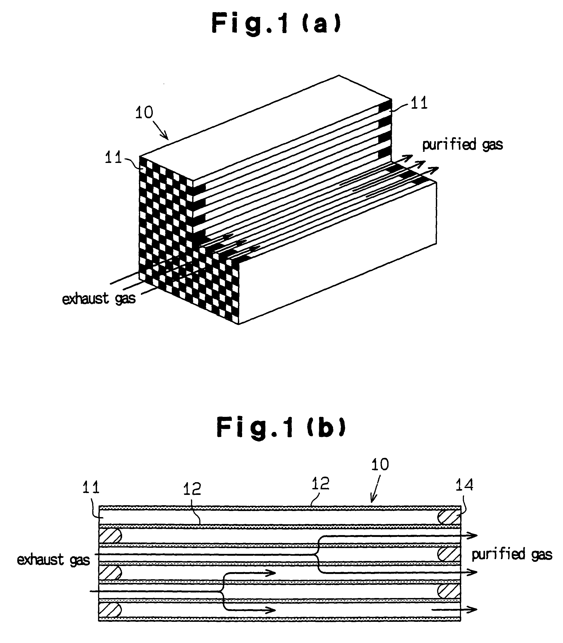
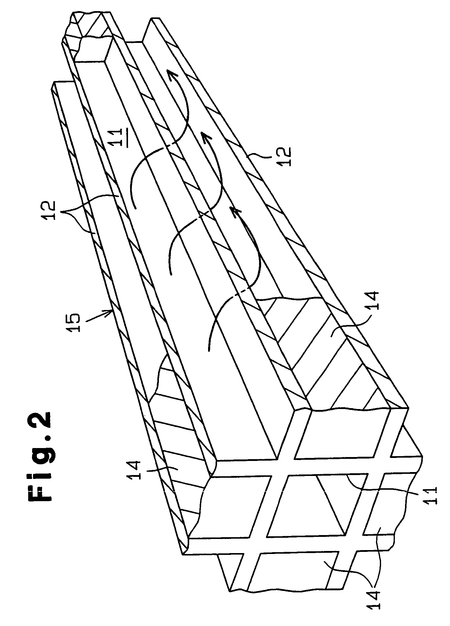
TECHNICAL FIELD[0001]This invention relates to a catalyst holding filter for purifying an exhaust gas of an engine. More particularly, the invention relates to a catalyst holding filter capable of efficiently conducting oxidation removal of carbon monooxide (CO) and hydrocarbon (HC) and reduction of nitrogen oxide (NOx) included in an exhaust gas.BACKGROUND ART[0002]Heretofore, as a catalyst holding filter for the purification of an exhaust gas in an automobile, there is, for example, one of purifying an exhaust gas of a diesel engine. As shown in FIG. 17(a) and FIG. 17(b), a catalyst holding filter 100 is used by forming cells 101 as a path of an exhaust gas from a porous silicon carbide sintered body in a honeycomb shape and alternately clogging these cells 101. It is common that the catalyst holding filter 100 is connected to an exhaust side of a diesel engine and particulates (PM: particulate matter) deposited on the filter 100 and HC, CO and the like are decomposed through oxid...

Claims


Application Information

Patent Timeline
Patent Type & Authority Patents(United States)
IPC IPC(8): B01D50/00A61B8/00B01D39/20B01D53/94B01J21/04B01J23/10B01J35/04B01J35/10B01J37/02G01S7/00G01S7/52G01S7/521G01S15/89
CPCB01D39/2068B01D53/945B01J35/04B01J35/10C04B35/62813C04B35/62886C04B35/62897B01D53/94Y02T10/22B01J21/04B01J23/10B01J37/0215C04B2235/3227C04B2235/3229C04B2235/3244C04B2235/3826C04B2235/5409C04B2235/72C04B2235/77C04B2235/80Y02T10/12B01J35/56
Inventor OHNO, KAZUSHIGETAOKA, NORIYUKI
Owner IBIDEN CO LTD
Learn More