Network-based service for the repair of IP multicast sessions
- Summary
- Abstract
- Description
- Claims
- Application Information
AI Technical Summary
Benefits of technology
Problems solved by technology
Method used
Image
Examples
Embodiment Construction
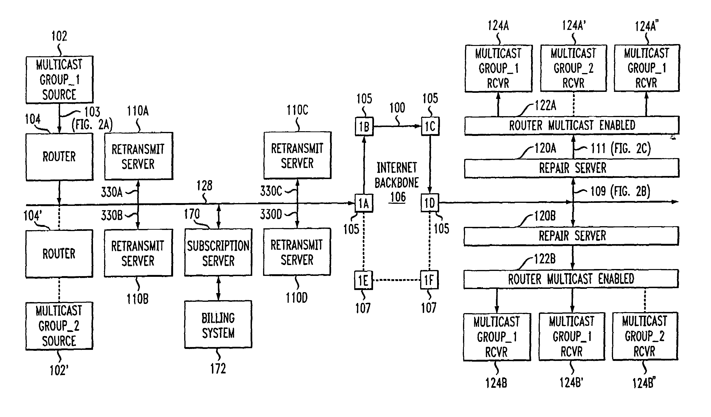
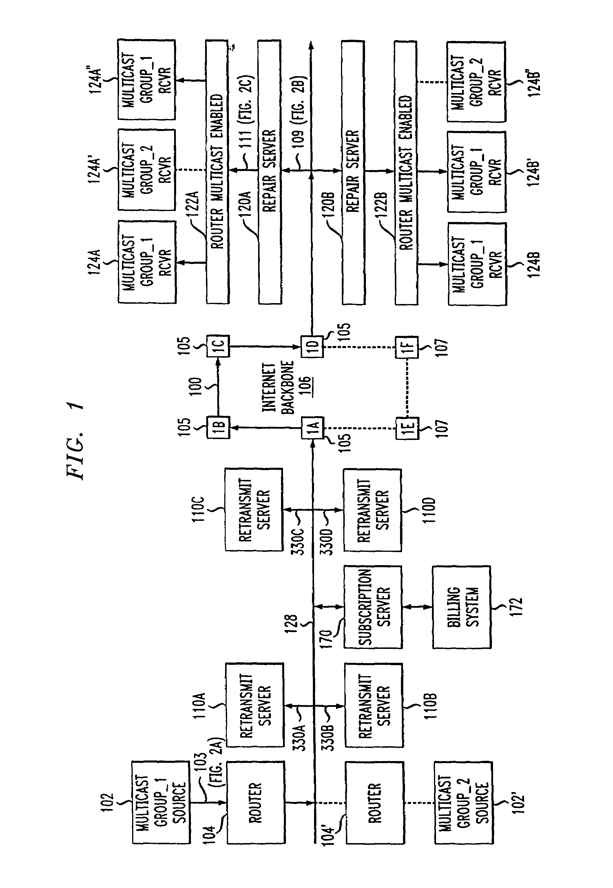
[0059]FIG. 1 is an overall network diagram showing a multicast source 102 that is transmitting a Group—1 multicast session 100, whose packets 103 are shown in FIG. 2A. FIG. 2A illustrates the packets 103 currently being output by the multicast source 102, with packets 281 to 290 being shown. The packets pass through the multicast enabled router 104 and are output on line 128 to the Internet backbone 106. A second multicast source 102′ is shown transmitting a second Group—2 multicast session onto the Internet backbone 106.
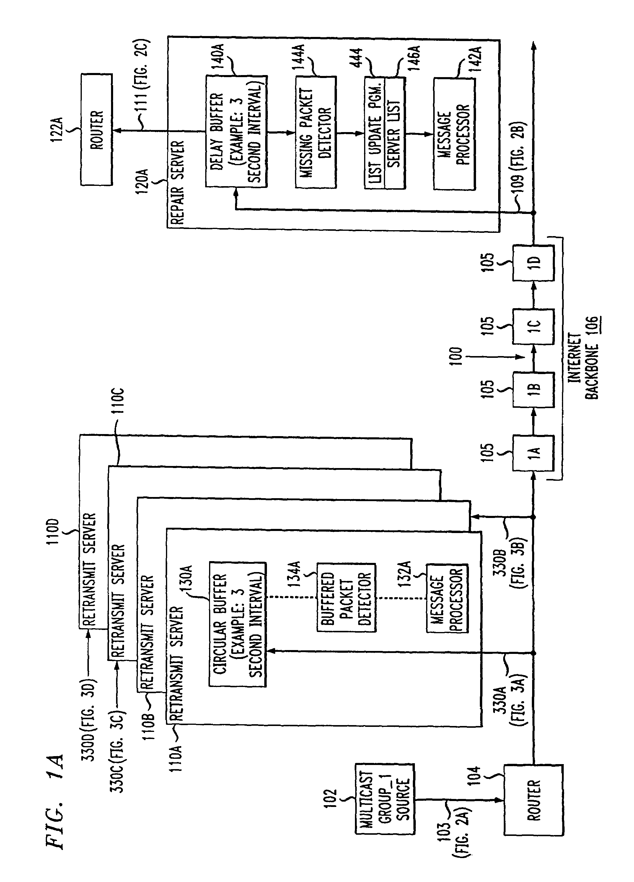
[0060]A plurality of retransmit servers 110A, 110B, 110C, and 110D are also shown connected to the Internet backbone 106. Each retransmit server, for example 110A in FIG. 1A, includes a circular buffer 130A that stores a running segment of the multicast Group—1 session received from the source 102, for example the most recent three second interval of the received session. The session packet stream 103 sent from the source 102 may undergo some packet losses by the ti...
PUM
 Abstract
Description
Claims
Application Information
 - R&D
- Intellectual Property
- Life Sciences
- Materials
- Tech Scout
- Unparalleled Data Quality
- Higher Quality Content
- 60% Fewer Hallucinations
Browse by: Latest US Patents, China's latest patents, Technical Efficacy Thesaurus, Application Domain, Technology Topic, Popular Technical Reports.
© 2025 PatSnap. All rights reserved.Legal|Privacy policy|Modern Slavery Act Transparency Statement|Sitemap|About US| Contact US: help@patsnap.com


