
Motor control system for the PWM control of an electric motor

a technology of motor control system and electric motor, which is applied in the direction of motor/generator/converter stopper, dynamo-electric converter control, instruments, etc., can solve the problems of inability to operate at 100% duty cycle, large number of cost-intensive components required for protective circuit, and component destruction, etc., to achieve the effect of improving accuracy and substantially reducing the number of components

Inactive Publication Date: 2009-09-15
FORD MOTOR CO
View PDF22 Cites 22 Cited by
  • Summary
  • Abstract
  • Description
  • Claims
  • Application Information

AI Technical Summary

Benefits of technology

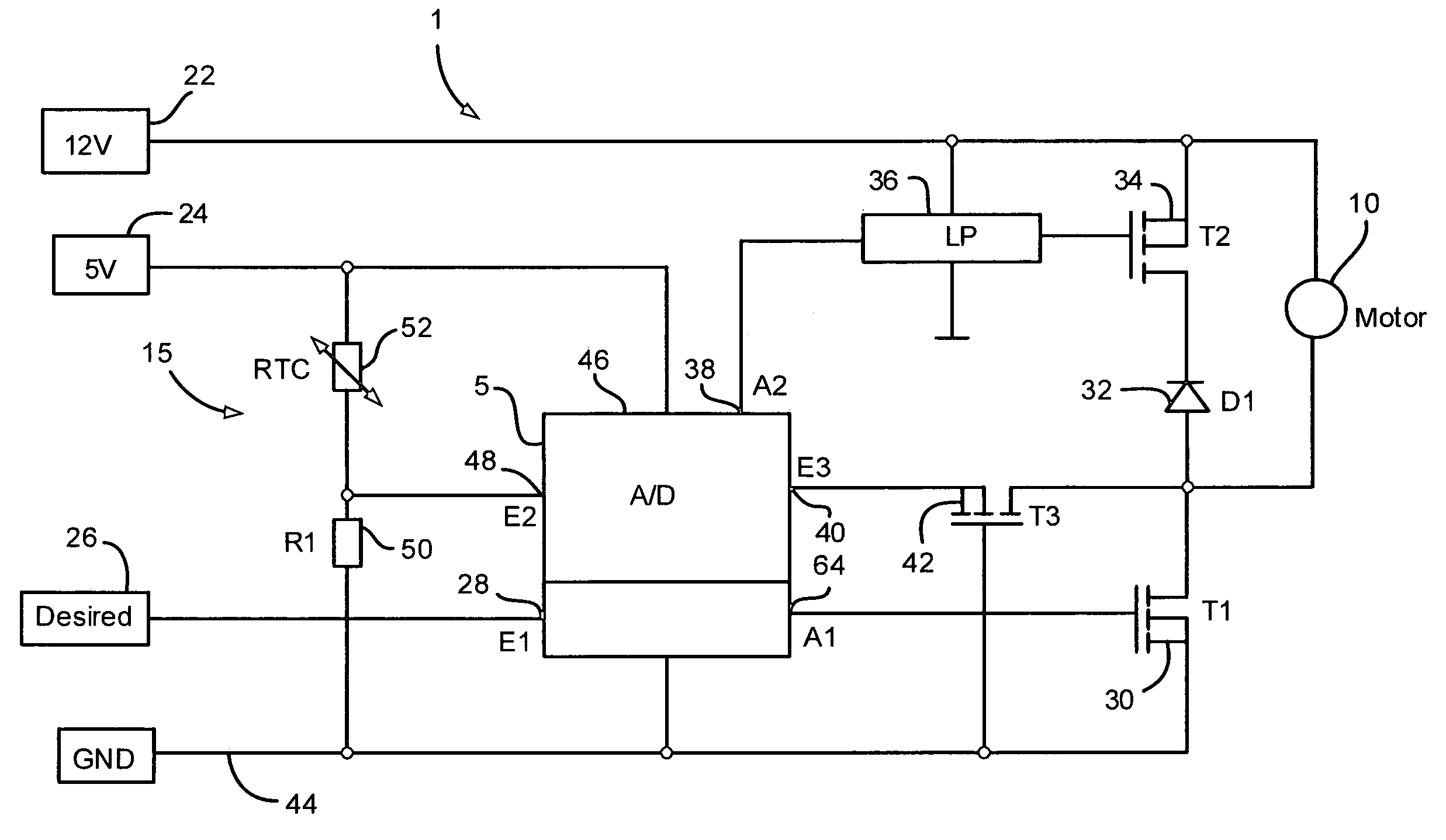
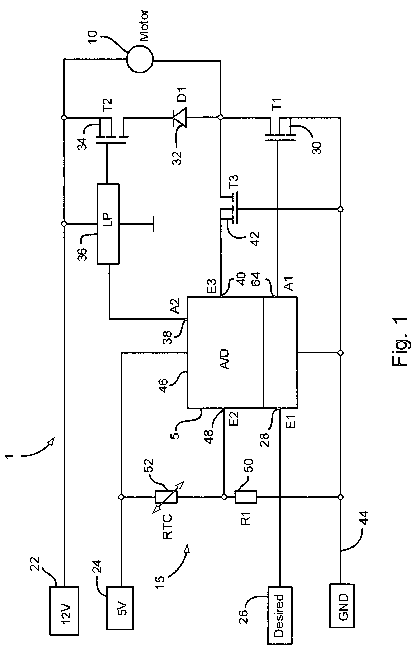
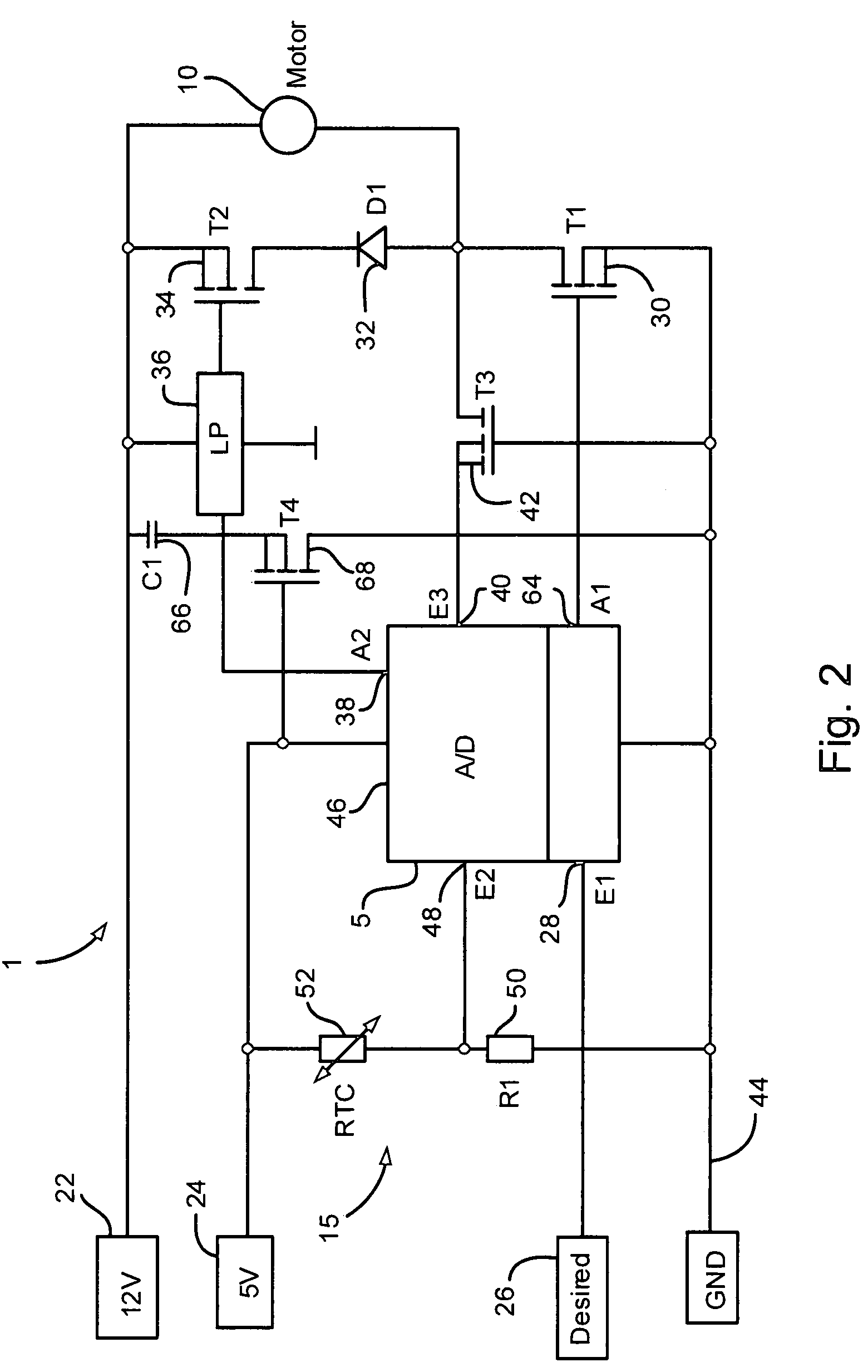
The present invention is about a motor control system for monitoring pulse width-modulated control for a DC electric motor. The system is designed to detect the voltage drop across the current-controlling field effect transistor, which is linked directly with the current at the motor. The system also includes a temperature sensor to detect the temperature of the transistor and determine its resistance. By monitoring the current and temperature, the system can accurately control the motor and avoid the disadvantages of previous protective circuits. The system can also compare the determined current with a predetermined reference value and remove the pulse width-modulated control if the current exceeds the reference value. The system has improved accuracy and requires fewer components, and it can function in all operating states of the pulse width-modulated control.

Problems solved by technology

However, if irregularities occur in such a circuit, uncontrolled overvoltages may occur in the circuit which can lead to destruction of components.
One disadvantage with the protective circuit known from DE 199 41 489 A1 is the comparatively large number of cost-intensive components which are required for the protective circuit.
Operation at a duty cycle of 100% is not possible.
This results in disadvantages in terms of the efficiency of the motor control system.

Method used


Image

  • Motor control system for the PWM control of an electric motor
  • Motor control system for the PWM control of an electric motor
  • Motor control system for the PWM control of an electric motor

Examples


third embodiment

[0032]FIG. 3 shows the motor control system 1 from FIG. 1. The arrangement described in FIG. 3 has many elements in common with that of FIG. 1, and to avoid unnecessary repetition of the description the same reference numbers have been used for common elements. Here, a collector-emitter path of a bipolar transistor (T5) 70 is arranged in the measuring line between the input 40 of the microprocessor 5 and the node between the power field effect transistor 30 and the anode of the freewheeling diode 32. The base of the bipolar transistor 70 is in this case connected to the positive terminal of the 5 volt rail via suitable resistors (not shown). The bipolar transistor 70 is used to minimize leakage currents via the microprocessor 5 in the off state of the motor control system shown, which leakage currents may be the cause of increased quiescent currents. Possible sources of such leakage currents may be, for example, electrolyte capacitors having a high capacitance which are connected in...

fourth embodiment

[0033]FIG. 4 shows the motor control system 1 shown in FIG. 1, having a power amplifier stage 16 being arranged in the control line, which extends between the output 64 of the microprocessor 5 and the gate of the field effect transistor 30. The arrangement described in FIG. 4 has many elements in common with that of FIG. 1, and to avoid unnecessary repetition of the description the same reference numbers have been used for common elements. This power amplifier stage 16 is likewise supplied from the 12 volt power supply system 22 of the motor vehicle, the voltage tap being connected on the high side at the node point between the drain terminal of the field effect transistor 34 and the cathode of the freewheeling diode 32. In this manner, the amplifier stage 16 is also reliably protected from polarity reversal of the 12 volt supply voltage by the polarity reversal protection circuit integrated in the freewheeling circuit. The amplifier stage 16 can in this case be constructed using su...

fifth embodiment

[0034]FIG. 5 now shows the motor control system 1, with which an improvement in the signal quality of the voltage signal present at the input 40 of the microprocessor 5 is achieved. The arrangement described in FIG. 5 has many elements in common with that of FIG. 1, and to avoid unnecessary repetition of the description the same reference numbers have been used for common elements. Owing to unavoidable induction phenomena at the DC electric motor 10 during pulse width-modulated operation, the rectangular control voltage produced by the motor control system 1 at the electric motor 10 is always superimposed by a high-frequency oscillation component. By way of example, this response is shown in FIG. 8. FIG. 8 shows the profile for the current over the source-drain path of the field effect transistor 30 over one cycle of the pulse width-modulated control as a function of time. It is clearly shown that a decaying oscillation in the current over the source-drain path occurs both when the ...


PUM


Abstract

The subject of the present invention is a motor control system having a monitoring circuit for monitoring PWM control for a DC electric motor, the PWM control comprising a power end stage having at least one field effect transistor, which controls the current at the DC electric motor. The motor control system is designed to monitor the current at the DC electric motor. The motor control system detects the voltage drop across the field effect transistor and comprises a temperature sensor for detecting the temperature of the field effect transistor. Furthermore, the motor control system is designed to determine the resistance of the field effect transistor from the detected temperature thereof, and to determine the current at the DC electric motor from the resistance of the field effect transistor and from the voltage drop across the field effect transistor.

Description

CROSS REFERENCE TO RELATED APPLICATION[0001]This application is based on, claims the benefit of and incorporates herein by reference German patent application no. DE 10 2006 029 332.0, filed Jun. 23, 2006.BACKGROUND OF THE INVENTION[0002]The present invention relates generally to a motor control system for monitoring pulse width-modulated (PWM) control for a direct current (DC) electric motor, in particular for a fan motor for use in the motor vehicle sector.[0003]German patent application DE 1 941 489 A1 has disclosed a protective circuit for a series circuit comprising a power semiconductor end stage and an inductive load, in parallel with which a freewheeling circuit comprising a freewheeling diode and a series-connected polarity reversal protection semiconductor switch is connected. The power semiconductor end stage can be switched on and off again as a function of a predetermined desired value with a pulse width-modulated control signal. The polarity reversal protection semicon...

Claims


Application Information

Patent Timeline
Patent Type & Authority Patents(United States)
IPC IPC(8): H02P23/00
CPCG01R19/0092H02H7/0833H02H9/047G01R31/2829
Inventor HAESTERS, ACHIMDIENHART, BERNDWASCHKIES, JOACHIMLINDEKE, GUIDOPETER, CORNELIUSPETER, LEGAL REPRESENTATIVE, ANGELIKA
Owner FORD MOTOR CO
Learn More