Method of manufacturing semiconductor device, and semiconductor device
a manufacturing method and semiconductor technology, applied in the field of metal oxide semiconductors, can solve the problems of insufficient carrier mobility and achieve the effects of preventing short channel effect, reducing manufacturing costs, and reducing manufacturing costs
- Summary
- Abstract
- Description
- Claims
- Application Information
AI Technical Summary
Benefits of technology
Problems solved by technology
Method used
Image
Examples
first embodiment
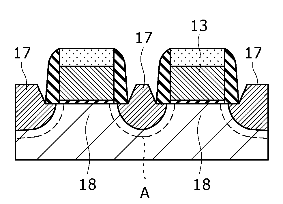
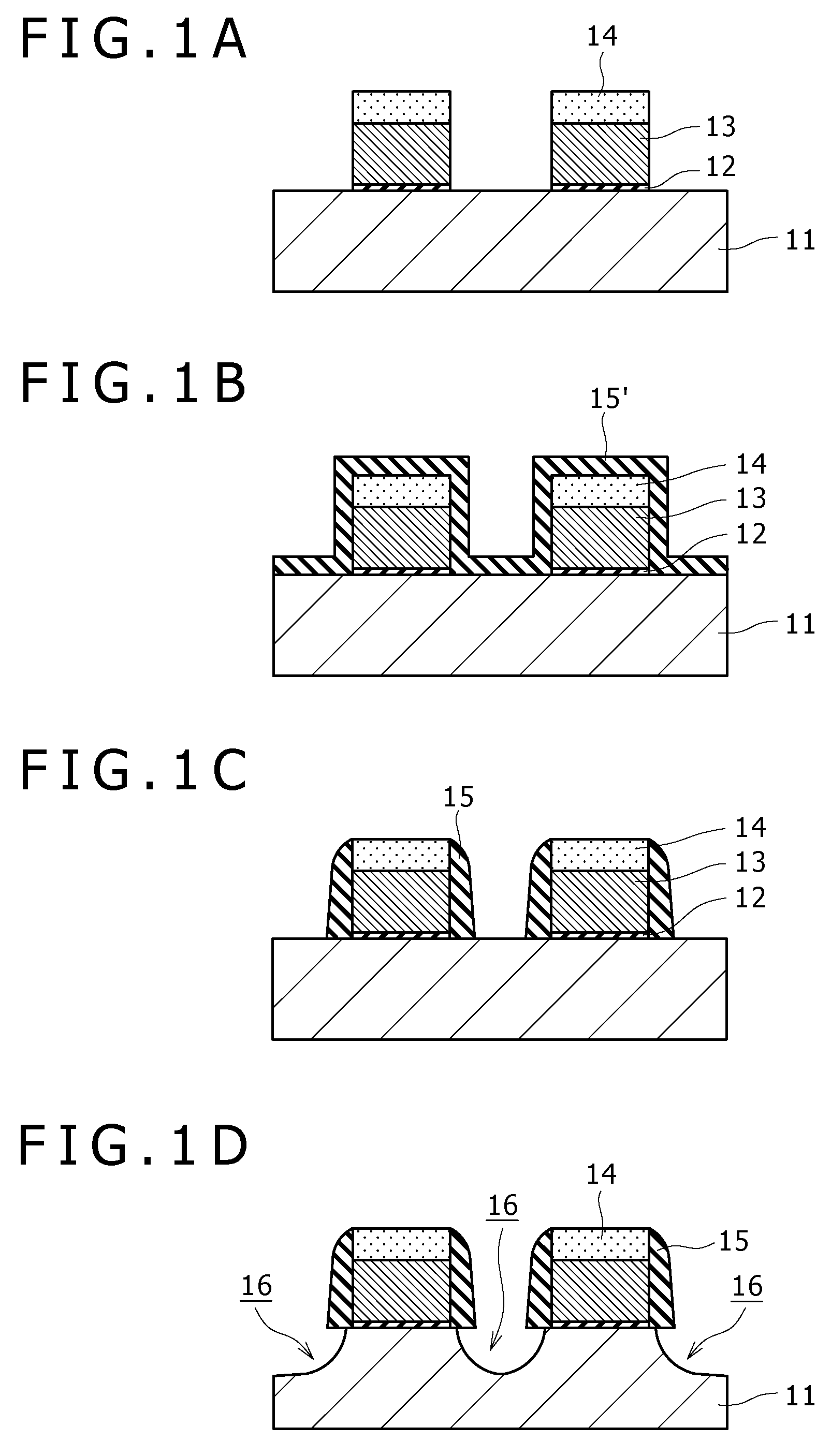
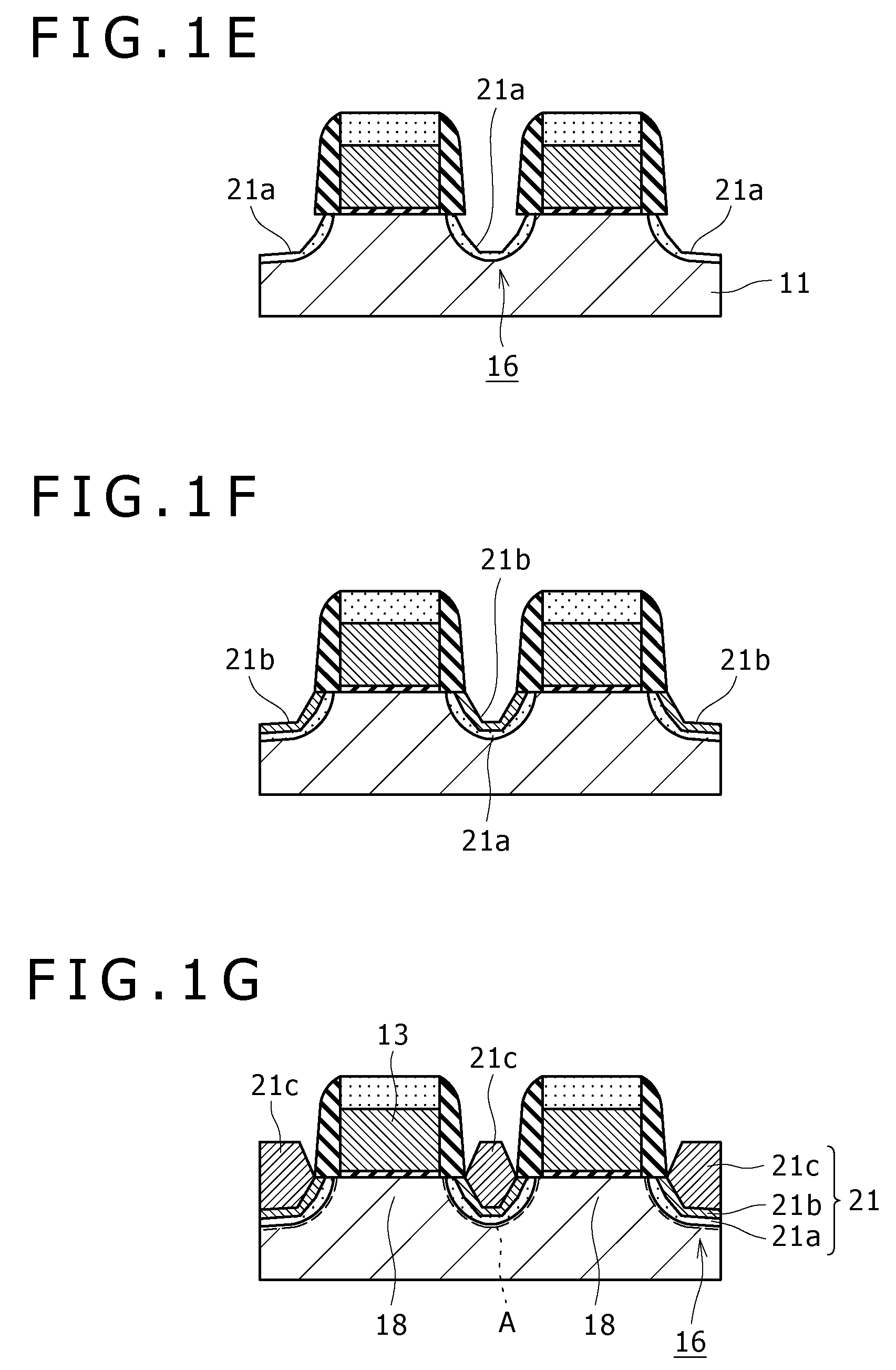
[0022]An embodiment of the method of manufacturing a semiconductor device pertaining to the present invention will be described below, taking the method of manufacturing a PMOSFET as an example and referring to the manufacturing step sectional diagrams in FIGS. 1A to 2G. Incidentally, in the following description, the same configurations as those described in the background of the invention above will be denoted by the same symbols as used above.
[0023]First, as shown in FIG. 1A, a silicon substrate 11 composed of single crystal silicon is prepared, and device isolation regions are formed on the face side thereof. In this case, for example, device isolation regions of the STI (shallow trench isolation) structure are formed, in which trenches are formed on the face side of the silicon substrate 11, and an insulating film composed of a silicon oxide film, for example, is buried in the trenches.
[0024]Next, on the silicon substrate 11 in each area isolated by the device isolation regions...
second embodiment
[0046]While the method of manufacturing a PMOSFET has been taken as an example in the description of the first embodiment above, in this embodiment a method of manufacturing an NMOSFET is taken as an example and description thereof will be made referring to FIGS. 2A to 2C. Incidentally, the steps up to the step of digging down the surface of a silicon substrate 11 are carried out in the same manner as the steps described referring to FIGS. 1A to 1D above.
[0047]In the case of manufacturing an NMOSFET, first, as shown in FIG. 2A, a silicon-carbon (SiC) layer (mixed crystal layer) composed of silicon (Si) and atoms (C) smaller in lattice constant than silicon and containing, for example, arsenic (As) as an impurity is epitaxially grown on the surfaces of recessed regions 16, i.e., on the surfaces of the dug-down portions of the silicon substrate 11.
[0048]In this case, also, the SiC layer is epitaxially grown so as to contain As with such a concentration gradient that the As concentrati...
modified example 1
[0062]While an example in which As is contained as an impurity in the SiC layer for forming the source / drain regions of the NMOSFET has been described in the second embodiment above, phosphorus (P) may be used, in place of As, as the impurity.
[0063]In this case, also, the first SiC layer 22a is formed in a film thickness of one to 30 nm so as to contain P as the impurity in a concentration in the range of 1×10¹⁸ to 1×1019 cm−3.
[0064]As for the film forming conditions for the first SiC layer 22a, DCS, SiH3CH3 diluted with hydrogen (H2) to one vol %, HCl, and phosphorus hydride (PH3) diluted with H2 to 50 ppm are used as film-forming gases, at gas flow rates of DCS / SiH3CH3 / HCl / PH3=ten to 100 / one to 50 / ten to 100 / one to 150 (ml / min), a treating temperature of 650 to 750° C., and a treating pressure of 1.3 to 13.3 kPa.
[0065]Next, on the first SiC layer 22a, a second SiC layer 22b is formed in a film thickness of one to 20 nm so as to contain P as an impurity with such a concentration gr...
PUM
| Property | Measurement | Unit |
|---|---|---|
| thickness | aaaaa | aaaaa |
| pressure | aaaaa | aaaaa |
| temperature | aaaaa | aaaaa |
Abstract
Description
Claims
Application Information
 - R&D
- Intellectual Property
- Life Sciences
- Materials
- Tech Scout
- Unparalleled Data Quality
- Higher Quality Content
- 60% Fewer Hallucinations
Browse by: Latest US Patents, China's latest patents, Technical Efficacy Thesaurus, Application Domain, Technology Topic, Popular Technical Reports.
© 2025 PatSnap. All rights reserved.Legal|Privacy policy|Modern Slavery Act Transparency Statement|Sitemap|About US| Contact US: help@patsnap.com


