
Method of establishing an oscillator clock signal

a technology of oscillator clock and signal, which is applied in the field of establishment of clocks and carriers, can solve the problems of inability to implement on chips, relatively expensive, and only over a narrow frequency range of vcxos, and achieve the effect of efficient and correct selection of signal components

Inactive Publication Date: 2009-02-24
TRAVIS CHRISTOPHER JULIAN
View PDF20 Cites 23 Cited by
  • Summary
  • Abstract
  • Description
  • Claims
  • Application Information

AI Technical Summary

Benefits of technology

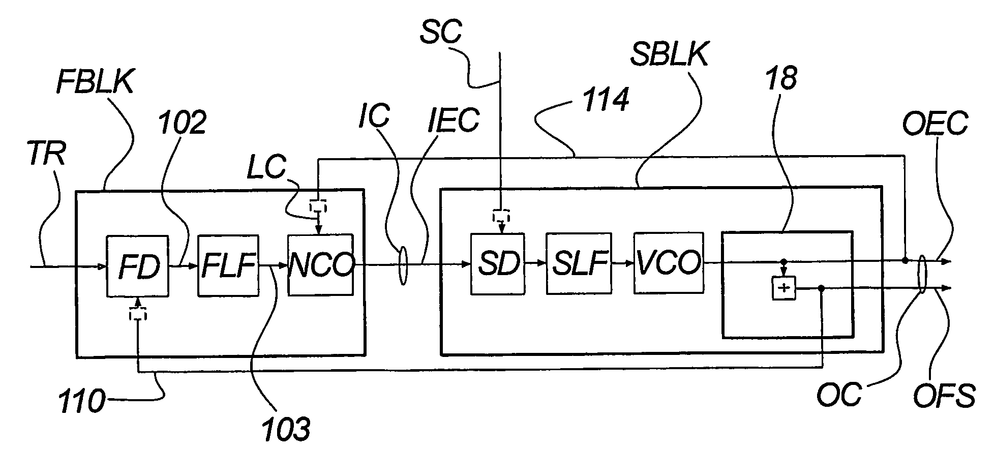
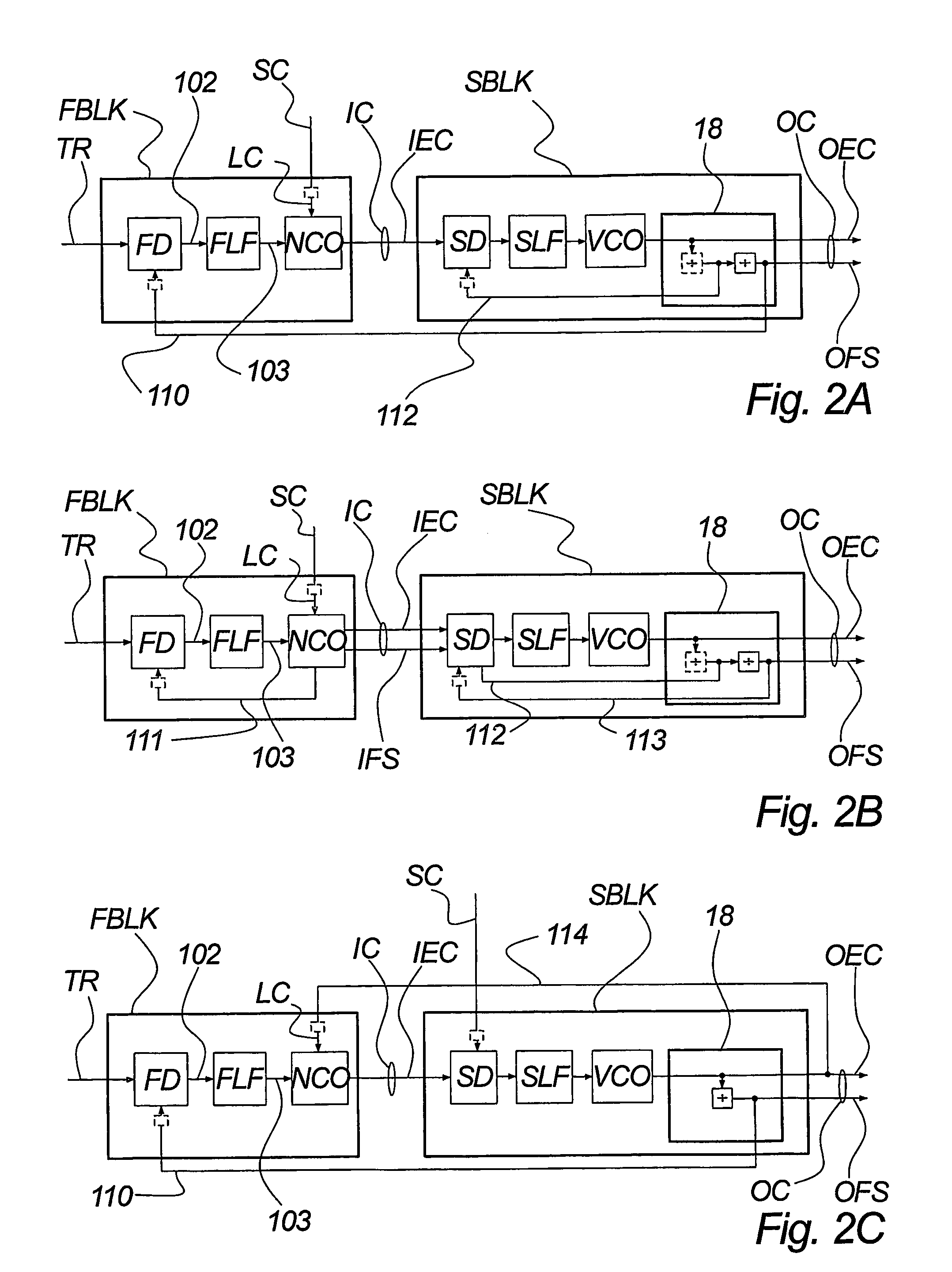
[0032]low cost implementation. The components, e.g. a numeric clock renderer adapted for the purpose of generating the intermediate clock on the basis of the input timing reference are by nature low-cost components, which may moreover be integrated on-chip. The components adapted for attenuating the jitter, typically the intrinsic jitter of the numeric clock renderer may also comprise relatively simple and low cost components in the sense that requirements to the bandwidth of the out filters are relatively relaxed in the sense that the intrinsic noise of the circuit according to the invention has been spectrum controlled previously to the final attenuation of the (typically intrinsic) jitter
[0163]According to the invention, this embodiment facilitates frames with relatively great lengths.

Problems solved by technology

However, VCXOs can be pulled only over a narrow frequency range.
Also, they are relatively expensive and cannot be implemented on chip.
Conversely, low-Q oscillators such as ring oscillators have wide frequency range and are fully integrable, but their high self-noise and their sensitivity to interference makes them only suited to use in wide-bandwidth PLLs.
However, it is not the case in most other applications.
Also it is often of relatively low quality, due to imperfect characteristics of that channel.
However, DDS is not without problems.
One is the cost of the DAC.
Others relate to finite wordlength effects, inadequate reconstruction filtering, and susceptibility to interference at the point where the sinewave is turned into a squarewave.
However, such number-controlled oscillators (NCOs) suffer greatly from beat-frequency effects.
Wholly numeric PLLs constructed around such oscillators generally suffer from an excess of high-frequency jitter, compared with analog PLLs.

Method used


Image

  • Method of establishing an oscillator clock signal
  • Method of establishing an oscillator clock signal
  • Method of establishing an oscillator clock signal

Examples


embodiment

PREFERRED EMBODIMENT

[0375]FIG. 19B shows a preferred embodiment of the Combined Detector of the present invention. As with FIG. 19A described above, and for the same reasons, this embodiment is not shown in the context of the second block of the cascade form of the Hybrid Synchronizer of the present invention.

[0376]This preferred embodiment comprises a reference synchronous state machine RSSM which is clocked by a reference event clock, being a first component IS1A of a first input signal IS1. It further comprises a feedback synchronous state machine FSSM which is clocked by a feedback event clock, being a first component IS2A of a second input signal IS2. It further comprises a combinatorial block CMB and a frame offset counter FOC. The reference state machine RSSM outputs a reference event count REC to the combinatorial block CMB, and this signal is also copied to the feedback state machine FSSM. Similarly, the feedback state machine outputs a feedback event count FEC to the combi...


PUM


Abstract

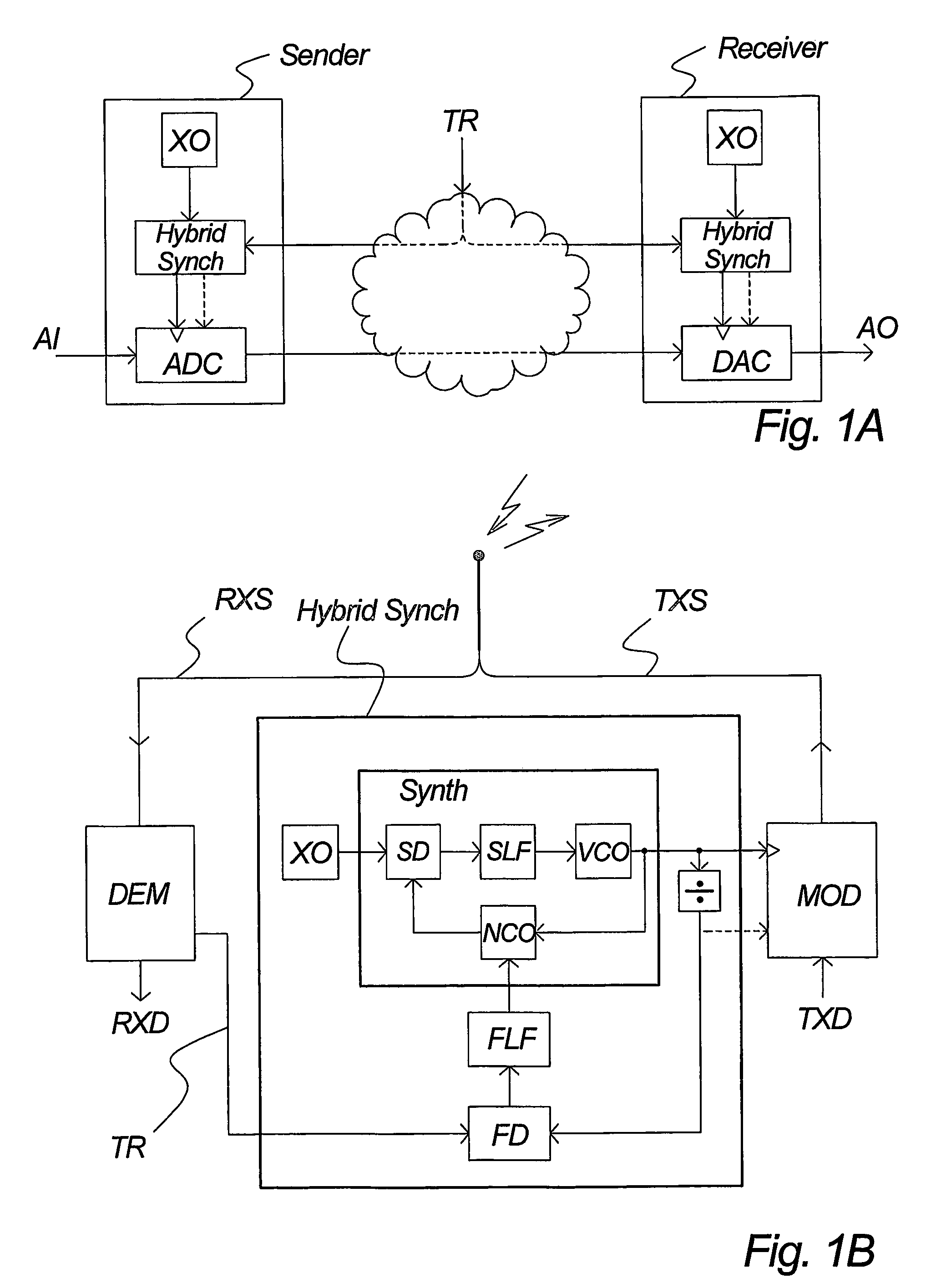
A hybrid numeric-analog clock synchronizer, for establishing a clock or carrier locked to a timing reference. The clock may include a framing component. The reference may have a low update rate. The synchronizer achieves high jitter rejection, low phase noise and wide frequency range. It can be integrated on chip. It may comprise a numeric time-locked loop (TLL) with an analog phase-locked loop (PLL). Moreover a high-performance number-controlled oscillator (NCO), for creating an event clock from a master clock according to a period control signal. It processes edge times rather than period values, allowing direct control of the spectrum and peak amplitude of the justification jitter. Moreover a combined clock-and-frame asynchrony detector, for measuring the phase or time offset between composite signals. It responds e.g. to event clocks and frame syncs, enabling frame locking with loop bandwidths greater than the frame rate.

Description

FIELD OF THE INVENTION[0001]The present invention relates to the establishment of clocks and carriers that are phase / time locked, frequency locked or frequency ratio locked to timing reference signals.BACKGROUND OF THE INVENTION[0002]In electronic systems, clocks and carriers abound. They are the heartbeat of synchronous circuits such as microprocessors. They are used to construct communications signals for transmission, and to recover data from received signals. They regulate the sampling of continuous-time signals, and the conversion of discrete-time signals into continuous-time form. They are modulated to carry information in elevated frequency bands, and are instrumental in demodulation.[0003]Clock quality has a direct bearing on system performance, e.g. operating margin, signal-to-noise ratio, spectral efficiency etcetera. Applications involving e.g. digital audio signals or radio-frequency communications can place particularly stringent limits on clock jitter and carrier phase...

Claims


Application Information

Patent Timeline
Patent Type & Authority Patents(United States)
IPC IPC(8): H03L7/00H03L7/07H03L7/085H03L7/087H03L7/099
CPCG06F1/025H03L7/07H03L7/085H03L7/087H03L7/0991H03L7/0994H04L7/0331G06F2211/902H03L7/235H03L7/083H03K3/0307H03L7/0995H03L7/10
Inventor TRAVIS, CHRISTOPHER JULIAN
Owner TRAVIS CHRISTOPHER JULIAN
Learn More