Semiconductor device and method for fabricating the same
a semiconductor and semiconductor technology, applied in the direction of semiconductor devices, electrical equipment, transistors, etc., can solve the problems of poor smoothness and difficulty in electric current flow, and achieve the effect of high carrier mobility at the channel layer and high carrier mobility
- Summary
- Abstract
- Description
- Claims
- Application Information
AI Technical Summary
Benefits of technology
Problems solved by technology
Method used
Image
Examples
first embodiment
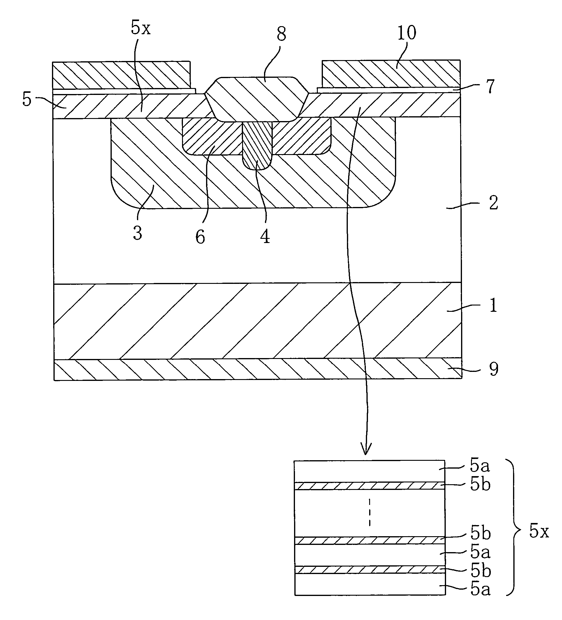
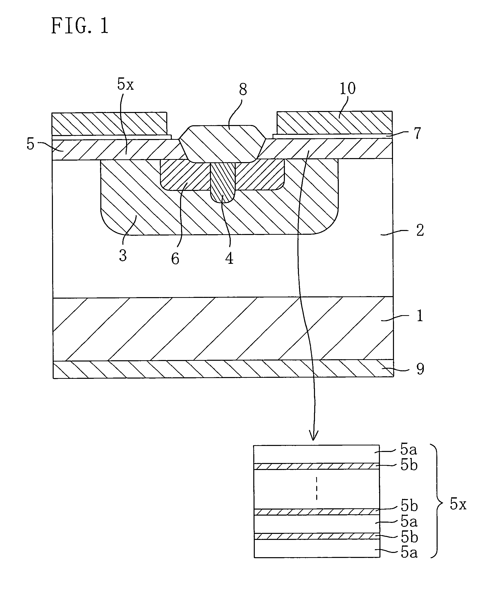
[0063]In the present embodiment, an accumulation-mode double-implantation MISFET that uses a bulk SiC substrate will be described as a first embodiment of the present invention. FIG. 1 is a cross-sectional view illustrating the structure of the double-implantation MISFET according to the first embodiment of the present invention. Although FIG. 1 shows only a partial cross-sectional structure of the MISFET, the planar structure thereof is similar to one disclosed in FIG. 2 or 10 of International Application PCT / JP01 / 07810, for example.
[0064]As shown in FIG. 1, the double-implantation MISFET includes: a low resistance SiC substrate 1 containing an n-type dopant at a concentration of 1×1018cm−3 or more; a high resistance SiC layer 2 provided on a principal surface of the SiC substrate 1 and containing an n-type dopant at a concentration of about 1×1015cm−3 to about 1×1016cm−3; a p-well region 3 formed by doping a part of a surface region of the high resistance SiC layer 2 with a p-type...
second embodiment
[0097]A semiconductor device according to a second embodiment of the present invention has a structure apparently similar to that of the double-implantation MISFET in the first embodiment shown in FIG. 1, and therefore, the structure of the MISFET according to the second embodiment is not shown. The MISFET of the present embodiment is greatly different from that of the first embodiment in that the surfaces of the high resistance SiC layer 2, the well region 3 and the source region 6 are not smoothed, and the surface smoothness is maintained by activation annealing performed with the high resistance SiC layer 2, the well region 3 and the source region 6 covered with a carbon film. Furthermore, the epitaxially grown layer 5 including the channel layer 5x is epitaxially grown on the high resistance SiC layer 2, the well region 3 and the source region 6. The channel layer 5x (the epitaxially grown layer 5) according to the present embodiment has an internal structure similar to that of ...
third embodiment
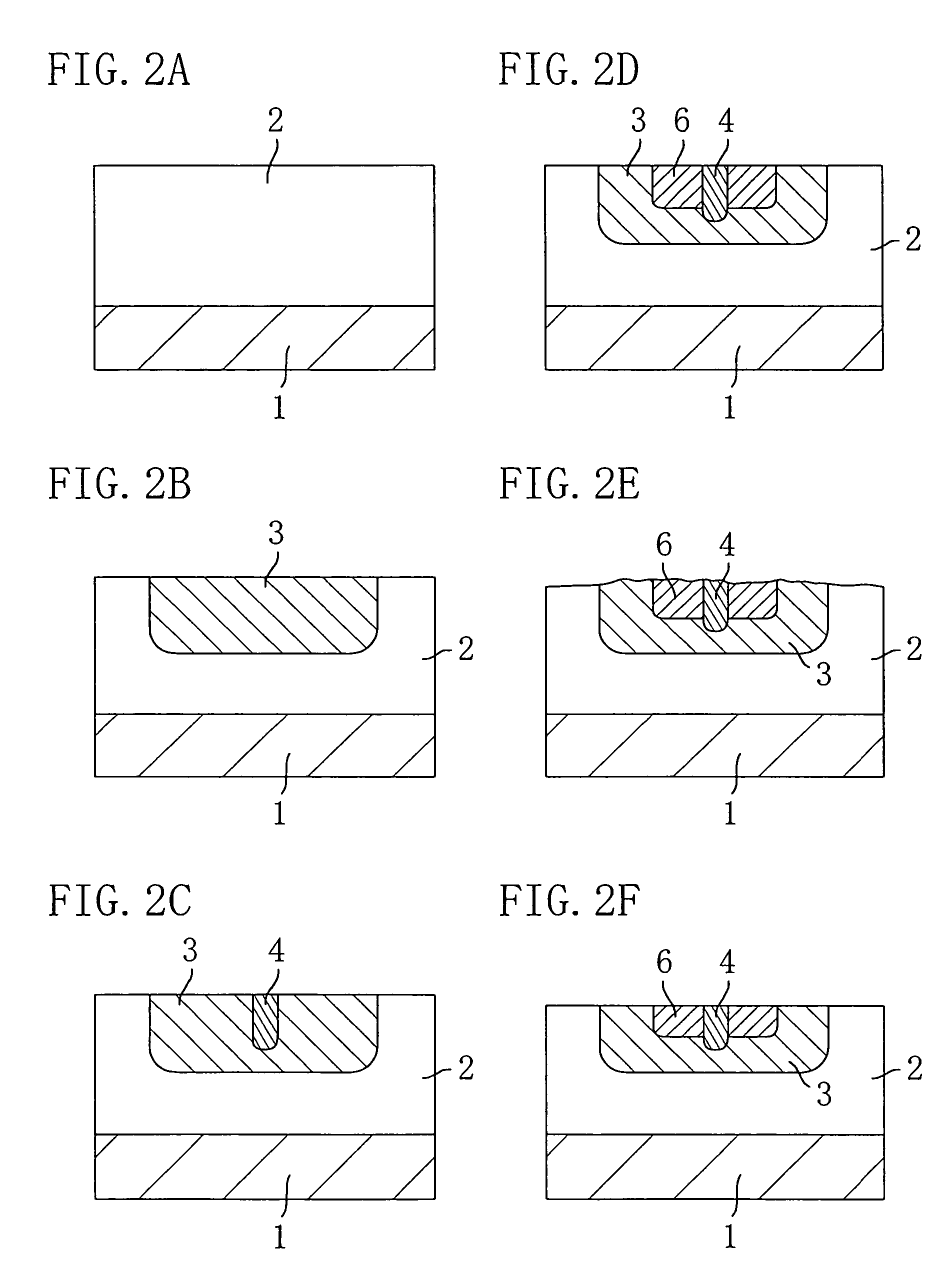
[0117]FIGS. 6A through 6F are cross-sectional views illustrating the process for fabricating a double-implantation MISFET according to a third embodiment of the present invention.
[0118]First, in the step shown in FIG. 6A, the step similar to that shown in FIG. 2A according to the first embodiment is carried out, thus epitaxially growing a high resistance SiC layer 2 on a principal surface of a SiC substrate 1 that is an off-substrate having an off angle of 8° from the (0001) plane of 4H—SiC.
[0119]Next, in the step shown in FIG. 6B, the step similar to that shown in FIG. 2C according to the first embodiment is carried out. Thus, a p+ contact region 4 is formed by implanting high-concentration p-type dopant ions into a part of a surface region of the high resistance SiC layer 2 in order to allow a p-well region and a source electrode, which will be subsequently formed, to be in electrical contact with each other. The p+ contact region 4 has a dopant concentration of about 5×1019cm−3 o...
PUM
| Property | Measurement | Unit |
|---|---|---|
| surface roughness | aaaaa | aaaaa |
| surface roughness | aaaaa | aaaaa |
| surface roughness | aaaaa | aaaaa |
Abstract
Description
Claims
Application Information
 - R&D
- Intellectual Property
- Life Sciences
- Materials
- Tech Scout
- Unparalleled Data Quality
- Higher Quality Content
- 60% Fewer Hallucinations
Browse by: Latest US Patents, China's latest patents, Technical Efficacy Thesaurus, Application Domain, Technology Topic, Popular Technical Reports.
© 2025 PatSnap. All rights reserved.Legal|Privacy policy|Modern Slavery Act Transparency Statement|Sitemap|About US| Contact US: help@patsnap.com


