
Hard coating and machining tool disposed with hard coating

a technology of hard coating and machining tool, which is applied in the field of hard coating, can solve the problems of not being suggested, not offering sufficient high performance in cutting composite materials, and doping with boron for diamond coating disposed on the surface of such as a machining tool body, and achieves the effects of improving the oxidation resistance of the diamond layer, and reducing the risk of oxidation

Active Publication Date: 2008-10-07
OSG
View PDF15 Cites 19 Cited by
  • Summary
  • Abstract
  • Description
  • Claims
  • Application Information

AI Technical Summary

Benefits of technology

[0020]In this hard coating, since the diamond coating disposed on the surface of such as a tool body is doped with boron, the diamond coating procures electrical conductivity. This causes coating with sufficiently electrical conductivity characteristics from the early period of the coating process, and therefore causes high strength of adhesion of the outer layer of the intermetallic compound to the diamond layer upon disposing the outer layer by the PVD method. Furthermore, improvement in oxidation resistance of the diamond layer itself by being doped with boron and the presence or covering of the outer layer cause extensive improvement in oxidation resistance. This provides superior durability by preventing flaking or early wearing of the coating by oxidation in cutting of the composite material including a material of iron series or in cutting of the heat-resistant alloy such as a titanium alloy with the cutting point at a high temperature.
[0021]In the third aspect of the invention, the diamond microcrystal causes evenness of the surface comparing to the conventional diamond layer, therefore, causes improvement in evenness of the surface (low coarseness of the surface) of the outer layer on the diamond layer and of the machined surface of the workpiece if applied to the diamond layer on the surface of a machining tool.
[0022]In the sixth aspect of the invention, thickness of the diamond layer in a range of 8-20 μm and thickness of the outer layer in a range of 1-5 μm causes improvements in wear resistance due to the diamond layer, sufficient adhesion of the diamond layer to the tool substrate and sufficient adhesion of the outer layer to the diamond layer, therefore, this preferably prevents flaking or removing of the diamond layer and the outer layer.
[0023]The machining tool that the above hard coating is disposed on the surface of the body according to the ninth aspect of the invention substantially achieves the effects as described above.
[0025]While hard tool material such as cemented carbide is preferably used for the body to be coated with hard coating for the machining tool, other tool material such as high-speed steel or ceramics may be used. The predetermined pretreatment as the surface roughening treatment or coating of other coating as a substrate on the surface of the tool body may be conducted for high adhesion.

Problems solved by technology

Although these diamond-coated tools have very high hardness, superior wear resistance and adhesion resistance, they often does not offer sufficiently high performance in cutting of the composite material including a material of iron series or in cutting of a material with its cutting point at a high temperature due to their low oxidation resistance.
Doping with boron for the diamond coating disposed on the surface of such as a machining tool body, however, has not been suggested yet.
Substantial insulation of diamond itself causes low strength of adhesion as a result of insufficient electrical conductivity characteristics from the early period of the coating process upon disposing an outer layer of such as TiAlN on the diamond coating by the PVD method, and causes insufficient durability as a result of flaking or removal of the outer layer in the early period of cutting.

Method used


Image

  • Hard coating and machining tool disposed with hard coating
  • Hard coating and machining tool disposed with hard coating
  • Hard coating and machining tool disposed with hard coating

Examples


Embodiment Construction

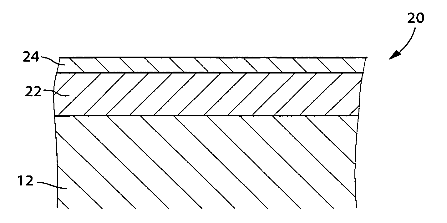
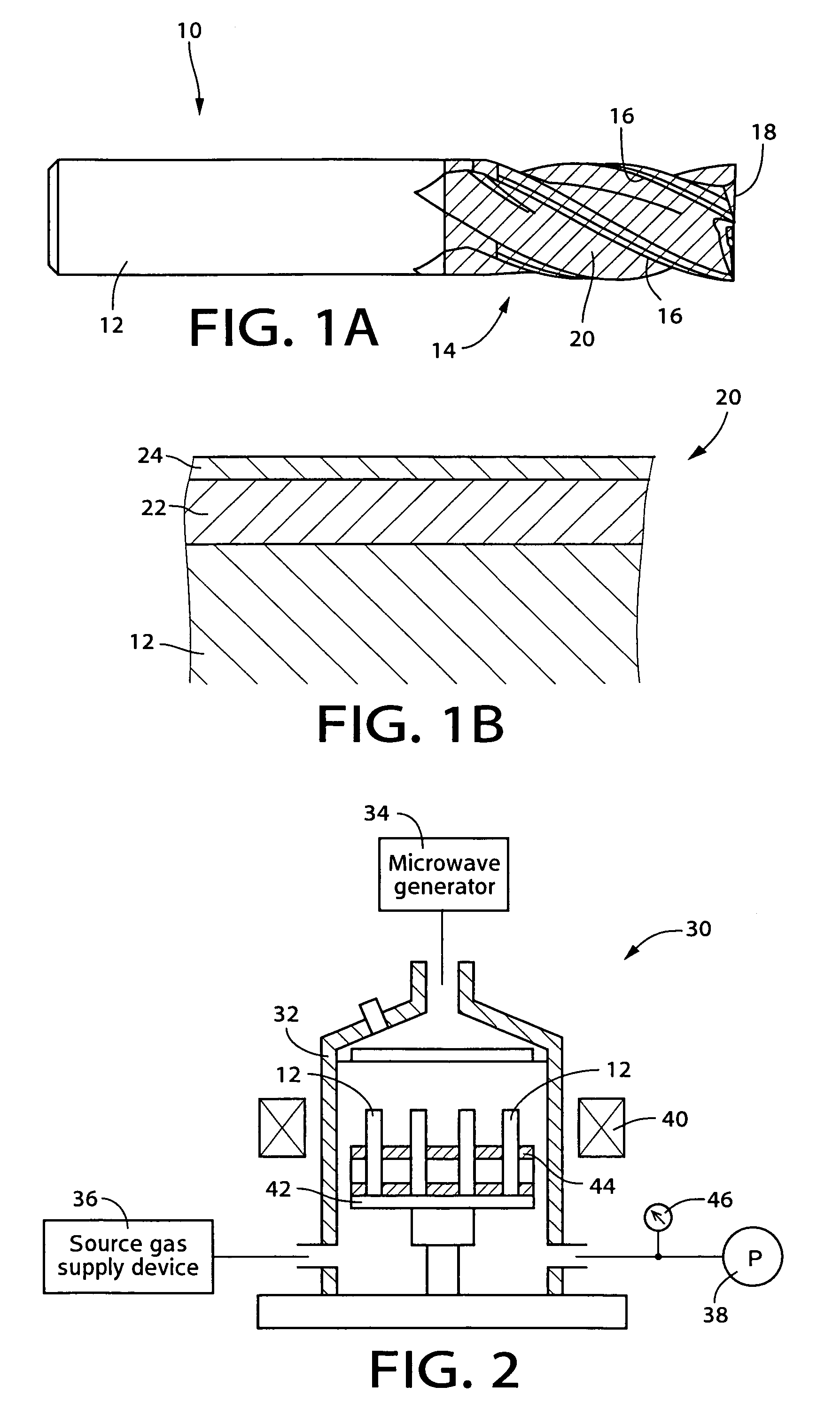
[0044]Hereinafter, there will be described the present invention by reference to the drawings. FIG. 1A illustrates an end mill 10 according to the invention in a front view as viewed from the perpendicular direction to the axis of the end mill 10 and FIG. 1B illustrates an adjacent portion to the surface of a cutting edge 14 of the end mill 10 in FIG. 1A in a sectional view. The end mill 10 is a square end mill having four cutting edges. A tool substrate 12 or a body of the end mill 10 is made of cemented carbide and the tool substrate 12 has a shank and the cutting part 14 that are integrally formed. The cutting part 14 corresponds to the machining portion or a main body and is provided with peripheral cutting edges 16 and end cutting edges 18 as cutting edges. The cutting part 14 is coated with the hard coating 20. The oblique lines in FIG. 1A show the area corresponding to the surface of the tool substrate 12 coated with the hard coating 20.

[0045]The hard coating 20 includes the ...


PUM

PropertyMeasurementUnit
crystal grain diameteraaaaaaaaaa
thicknessaaaaaaaaaa
thicknessaaaaaaaaaa

Abstract

A hard coating that is to be disposed on a surface of a body includes a diamond layer which includes a plurality of diamond grains and is doped with boron, and an outer layer which includes an intermetallic compound and is disposed on the diamond layer by a physical vapor deposition method.

Description

[0001]This application is based on Japanese Patent Application No. 2004-349152 filed Dec. 1, 2004, the contents of which are incorporated hereinto by reference.BACKGROUND OF THE INVENTION[0002]1. Field of the Invention[0003]The present invention relates to a hard coating that is to be disposed on a surface of a body of such as a machining tool, especially, to the art of disposing an outer layer on a diamond layer by the PVD method.[0004]2. Description of Related Art[0005]A diamond-coated tool coated with a diamond coating on the body made of such as cemented carbide is suggested for a cutting tool such as an end mill, a turning tool, a tap, a drill or other tools. JP 2519037B and JP 2002-79406A disclose examples of such tools. Although these diamond-coated tools have very high hardness, superior wear resistance and adhesion resistance, they often does not offer sufficiently high performance in cutting of the composite material including a material of iron series or in cutting of a m...

Claims


Application Information

Patent Timeline
Patent Type & Authority Patents(United States)
IPC IPC(8): B32B9/00
CPCB23B51/02B23C5/10B23G5/06C04B41/009C04B41/52C04B41/89C23C14/0641C23C14/0664C23C16/274C23C16/278C23C28/044C04B41/4531C04B41/5002C04B41/5094C04B41/4529C04B41/5068C04B41/5053C04B41/522C04B35/00Y10T428/24975B23B2224/32B23B2224/36B23B2226/31B23B2226/315B23B2228/04B23B2228/10B23B2224/24Y10T428/252Y10T428/24942Y10T428/24983Y10T428/265Y10T428/30Y10T407/27
Inventor HANYU, HIROYUKITOIHARA, TAKAOMISUGITA, HIROAKI
Owner OSG
Learn More