
Electrostatic chuck and substrate fixing method using the same

a technology of electrostatic chuck and substrate, which is applied in the direction of electrostatic holding devices, manufacturing tools, mechanical devices, etc., can solve the problems of reducing throughput, deteriorating surface, and insufficient electrostatic adsorption force to the substrate with a uniform thickness, so as to improve the uniformity of electrostatic adsorption force acting on the substrate, improve the exposure accuracy, and improve the effect of surface flatness

Active Publication Date: 2008-07-01
ADVANTEST CORP
View PDF18 Cites 6 Cited by
  • Summary
  • Abstract
  • Description
  • Claims
  • Application Information

AI Technical Summary

Benefits of technology

[0013]An object of the present invention is to provide an electrostatic chuck, and an substrate fixing method using the electrostatic chuck, which can hold substrates with various shapes, such as a substrate which has a partially thicker portion and a partially thinner portion as well as a substrate which has a uniform thickness, by use of sufficient electrostatic adsorption force, without lowering the throughput, and while maintaining the flatness of the surface.
[0017]A substrate (membrane substrate) which, for example, has a partially thinner portion in one of the center region and the peripheral region and a partially thicker portion in the other, is placed on the electrostatic chuck having the aforementioned configuration. In such a case, the voltage is applied selectively only to electrodes located in the portion where the membrane substrate is thicker as in a case of the substrate fixing method using the electrostatic chuck according to the present invention, and electrodes located in the portion where the membrane substrate is thinner is grounded, electrostatic adsorption force acts in the portion where the thickness of the membrane substrate is thicker so that the substrate is fixed. In addition, no electrostatic attraction is caused to act in the portion where the thickness of the membrane substrate is thinner so that the thinner portion does not deflect. This enables the flatness of the surface of the membrane substrate to be secured. For this reason, in a case where this electrostatic chuck is used, for example, in order to hold a membrane mask substrate with which to form an electron beam exposure mask, precision in exposure can be improved. On the other hand, when a substrate with a uniform thickness is placed, the voltage is applied to all the electrodes, electrostatic adsorption force acts on the entire substrate. Thus electrostatic adsorption force sufficient to hold the substrate can be obtained.
[0018]Furthermore, in a case where a direct current power supply is intended to be connected to each pair of electrodes, the direct current power supply is connected in a way that voltage of a different polarity is applied to a neighboring electrode. This enables uniformity in the surface of electrostatic adsorption force which acts in the substrate to be increased. Accordingly, the flatness of the surface can be improved.
[0019]In the aforementioned manner, a single electrostatic chuck can process substrates with various shapes while maintaining the flatness of the surface of the substrate, and while holding the substrate with sufficient electrostatic adsorption force. For this reason, electrostatic chucks do not have to be changed depending on difference in shape of substrates. Accordingly, the throughput can be improved.
[0020]Moreover, if the aforementioned electrostatic chuck is applied to transferring means, such as a robot, which needs to hold a substrate in a low pressure atmosphere, deformation could be prevented from occurring in the membrane substrate while the membrane substrate is being transferred. Furthermore, the substrate with a uniform thickness can be transferred while sufficient electrostatic adsorption force to the substrate being maintained.

Problems solved by technology

For this reason, it is likely that the portion where the thickness of the membrane mask substrate is thinner will deflect so that the flatness of the surface is deteriorated.
In this case, however, it is likely that electrostatic adsorption force to the substrate with a uniform thickness will become insufficient, since an area where the membrane mask substrate is adsorbed to the substrate placement surface of the electrostatic chuck is small in spite of the relatively heavy weight of the substrate.
However, the changing of the electrostatic chucks causes considerable inconvenience, thus lowering the throughput.

Method used


Image

  • Electrostatic chuck and substrate fixing method using the same
  • Electrostatic chuck and substrate fixing method using the same
  • Electrostatic chuck and substrate fixing method using the same

Examples


first embodiment

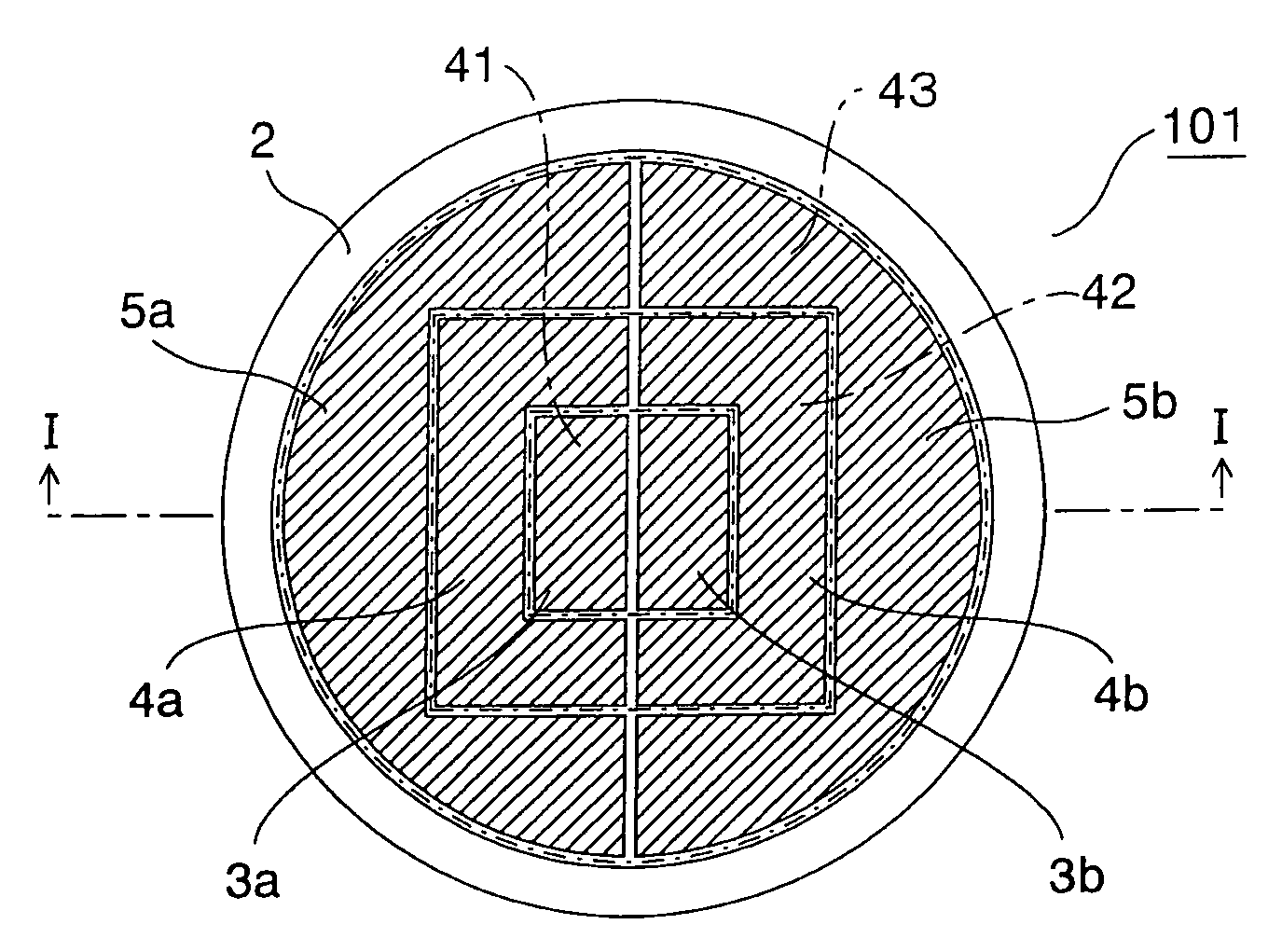
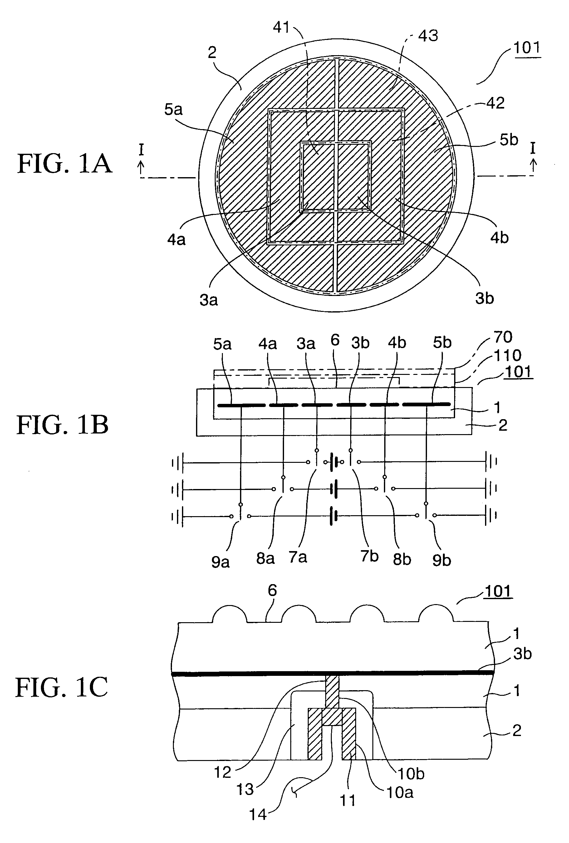
[0029]FIG. 1A is a plan view of an electrostatic chuck according to a first embodiment of the present invention. FIG. 1A shows an arrangement of, in particular, three pairs of electrodes. FIG. 1B is a cross-sectional view taken along the I-I line in FIG. 1A. FIG. 1B also shows how direct current power supplies are connected to the plurality of pairs of electrodes. FIG. 1C is a partial, enlarged, cross-sectional view showing a structure of a part where a wire is connected to each electrode of the electrostatic chuck toward the outside of the electrostatic chuck. Incidentally, in FIG. 1A, there are omissions of an illustration of an alumina member on the electrodes and an illustration of a substrate.

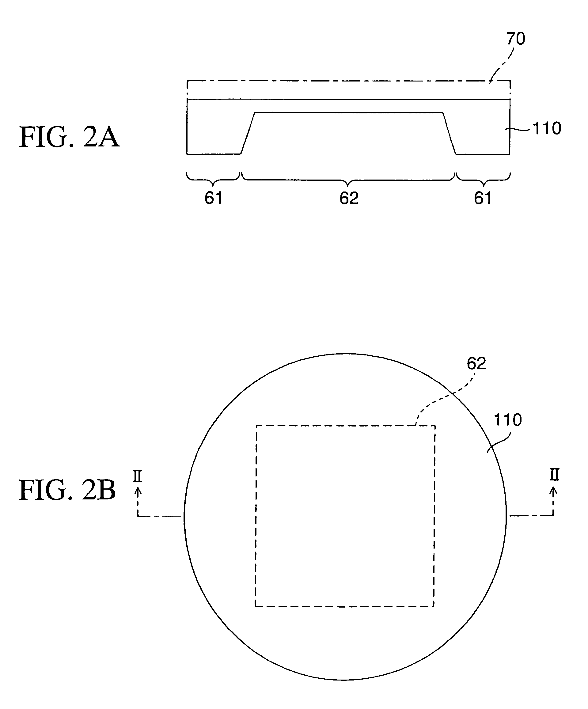
[0030]FIGS. 2A and 2B are respectively diagrams showing a membrane mask substrate which is placed, and held, on the electrostatic chuck. FIGS. 2A and 2B are respectively a cross-sectional view, and a top view, showing the membrane mask substrate. FIG. 2A is a cross-sectional view taken alo...

second embodiment

[0062]Next, descriptions will be provided for a second embodiment of the present invention with reference to FIGS. 5A and 5B.

[0063]FIG. 5A is a plan view of an electrostatic chuck according to the second embodiment of the present invention. FIG. 5A shows an arrangement of, in particular, 4 pairs of electrodes. FIG. 5B is a cross-sectional view taken along the III-III line in FIG. 5A. FIG. 5B also shows how direct current power supplies are connected respectively to the four pairs of electrodes. Incidentally, FIG. 5A omits an illustration of alumina members on the respective electrodes and an illustration of the substrate.

[0064]What makes the second embodiment different from the first embodiment is that the electrodes of the electrostatic chuck 102 are configured of a pair of (a first electrode group constituted of) electrodes 23a / 23b which are arranged in a plane area in the center portion (center region) 44 inside the main body 21, and three pairs of (a second electrode group const...

third embodiment

[0076]Next, descriptions will be provided for an electrostatic chuck according to a third embodiment of the present invention with reference to FIGS. 6 and 7.

[0077]First of all, descriptions will be provided for an electrostatic chuck according to a first example of the third embodiment with reference to FIG. 6A. FIG. 6A is a top view of the electrostatic chuck.

[0078]What makes the electrostatic chuck 103 according to the first example of the third embodiment different from the electrostatic chuck 101 shown in FIG. 1A according to the first embodiment is that, as shown in FIG. 6A, the center region 48 has two pairs of electrodes 81a / 81b and 81c / 81d, one annular belt-shaped region 49 has two pairs of electrodes 82a / 82b and 82c / 82d, and the other annular belt-shaped region 50 has two pairs of electrodes 83a / 83b and 83c / 83d. In other words, each of the three regions has four electrodes. In this manner, the electrostatic chuck 103 has more electrodes than the electrostatic chuck 101 doe...


PUM


Abstract

The electrostatic chuck 101 where pairs of electrodes 3a / 3b, 4a / 4b and 5a / 5b to which voltages are applied are embedded in the main body 1, and where a substrate 110 is placed and held on the surface of the main body 1, includes a first electrode group constituted of one pair or more of electrodes 3a / 3b arranged in a center region 41 inside the main body 1, and a second electrode group constituted of one pair or more of electrodes 4a / 4b and 5a / 5b arranged in outer peripheral portions 42 and 43 surrounding the center region 41.

Description

CROSS-REFERENCE TO RELATED APPLICATION[0001]This application is based on and claims priority of Japanese Patent Application No. 2004-093184 filed on Mar. 26, 2004, the entire contents of which are incorporated herein by reference.BACKGROUND OF THE INVENTION[0002]1. Field of the Invention[0003]The present invention relates to an electrostatic chuck and a substrate fixing method using the same. More specifically, the present invention relates to an electrostatic chuck which holds, and fixes, a substrate subject to a treatment in a vacuum processing apparatus such as a charged particle beam exposure apparatus, and to a substrate fixing method using the electrostatic chuck.[0004]2. Description of the Prior Art[0005]With regard to a low pressure processing apparatus, such as a deposition apparatus by use of low pressure CVD and sputtering, an etching apparatus and an electron beam exposure apparatus, which performs a process under a low pressure, electrostatic chucks have been used as me...

Claims


Application Information

Patent Timeline
Patent Type & Authority Patents(United States)
IPC IPC(8): H02N13/00B25B11/00H01H1/00H01J37/32H01L21/263H01L21/68H01L21/683
CPCH01L21/6833Y10T279/23
Inventor HAYAKAWA, HIROFUMI
Owner ADVANTEST CORP
Learn More