
High frequency low noise phase-frequency detector and phase noise reduction method and apparatus

a detector and low-noise technology, applied in the direction of angle demodulation by phase difference detection, automatic control of pulses, angle demodulation by oscillation conversion, etc., can solve the problems of limiting the phase noise performance of phase noise synthesizers, significant deformation, and degradation of phase noise performance. , to achieve the effect of less nois

Inactive Publication Date: 2008-06-10
ARRIS ENTERPRISES LLC
View PDF8 Cites 73 Cited by
  • Summary
  • Abstract
  • Description
  • Claims
  • Application Information

AI Technical Summary

Benefits of technology

The present invention provides faster and more efficient frequency discriminators and comparators for use in high-speed applications. It also allows for FM demodulation over a wide frequency range and the use of bi-level circuits for both digital and analog functions. The invention can be integrated onto a single chip and allows for control over operating frequency and time delay. Additionally, the invention provides a less noisy PFD solution for low phase-noise PLL applications. Overall, the invention improves the performance and reliability of frequency synthesizers and receivers.

Problems solved by technology

The multiplied noise will then phase modulate the voltage controlled oscillator (VCO) and will significantly degrade and limit its phase noise performance.
This noise multiplication is often the key factor causing degradation of phase noise performance in synthesizers.
During acquisition of the phase lock, the phase detector (PD) alone may not be able to provide an adequate steering signal necessary for locking, and additional means for assisting the frequency acquisition is often necessary.
The frequency discriminators of the prior art used in frequency synthesizers are inherently limited in speed.
The relatively long propagation delays and settling times of the flip-flops limit the maximum speed (or frequency) of the FD operation, and thus indirectly limits the maximum comparison frequency in a PLL employing such an FD.
The limitations of these flip-flop based circuits are mainly related to speed (i.e., to the maximum operating frequency).
Their physical limitations are the set-up and hold times of the flip flops, the propagation delays from their Clock, Reset and D inputs to the outputs, as well as the usual propagation delays of the combinatorial logic and their interconnections.
Those limitations produce two types of artifacts associated particularly with the phase-detection, namely the “dead-zone” and the “blind-spot”.
Another disadvantage of performing phase detection using one of those PFDs is that they are quite noisy, and require a charge pump with a relatively narrow low-pass filter (or integrator) because the phase correction pulses to the charge pump may occur at very low frequencies.
Another disadvantage of the prior art FDs is that their gain (expressed in Volts / Hz) is low, and cannot be controlled.
The consequence is that when F.sub.ref and F.sub.in are very close to each other (i.e., close to lock condition) the steering voltage output (around ½ Vcc) would be extremely small, potentially slowing down the acquisition speed.
This approach is limited to lower FM carrier frequencies, where the limitation is imposed by analog to digital converters (ADC) speed, as well as by the computational speed.
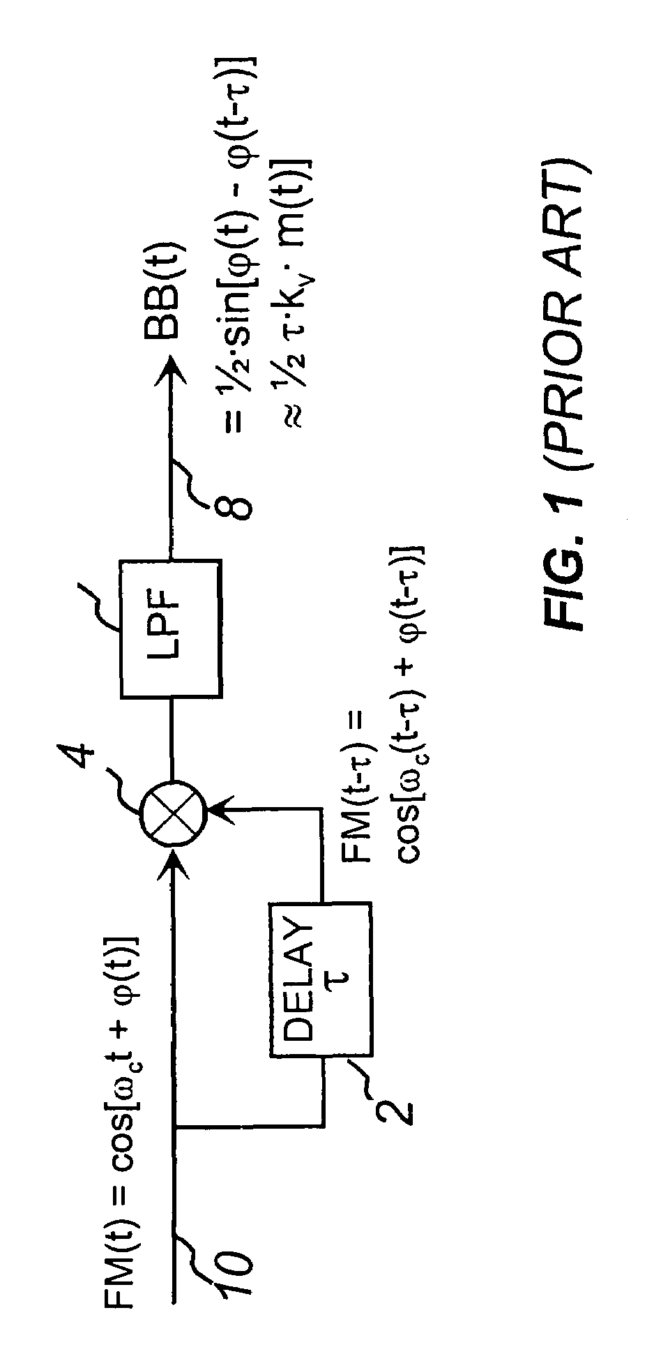
Furthermore, the delay must also produce a quadrature phase shift (90.degree.) at the center frequency .omega..sub.c (if the phase delay is not exactly 90.degree., the demod would still work, but at reduced performance).
The specific requirement for phase quadrature imposes a practical limit for the use of this demod to a fixed frequency.
The problem of using this type of demodulator in frequency agile applications comes from the difficulty in achieving flat group delay and maintaining a 90.degree. phase shift over broader range of carrier frequencies .omega..sub.c.
Furthermore, this solution is not suitable for integration into integrated circuits (ICs), due to difficulties in implementing a required time delay and phase shift inside the integrated circuit.
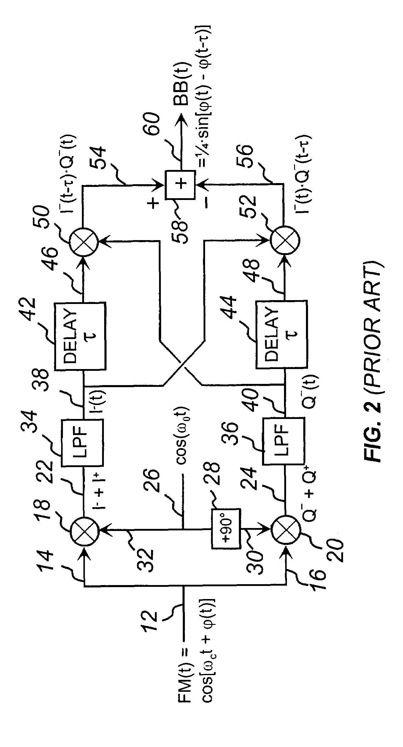
While the solution of FIG. 2 resolves the frequency agility issue, it is still not suitable for integration into integrated circuits (ICs), due to difficulties in implementing low pass filters inside the ICs.
Any amplitude and / or phase imbalance in the two paths 38 and 40 will cause degradation of the quality of the demodulated signal (i.e., the noise and distortion performance will degrade).
This places additional burden on low pass filter design and implementation for the prior art.

Method used


Image

  • High frequency low noise phase-frequency detector and phase noise reduction method and apparatus
  • High frequency low noise phase-frequency detector and phase noise reduction method and apparatus
  • High frequency low noise phase-frequency detector and phase noise reduction method and apparatus

Examples


example 1

[0205]With passive mixers @ RF frequency of 5 GHz the PFD 500 achieves 180 dBc / Hz CNR at RF: LO level at input 530=20 dBm (translates to 17 dBm LO drive level at I / Q mixers after quadrature split); signal level at input 118=18 dBm, which translates to 15 dBm at I / Q mixers inputs, after 3 dB loss in quadrature splitter; thermal noise=−174 dBm / Hz; Total Loss from input 118 to output 128=12 dB=3 dB (quadrature split loss)+6 dB (I / Q mixers loss) −3 dB (coherent signal addition)+6 dB (mixer 126); CNR=18 dBm+174 dBm / Hz−12 dB=180 dBc / Hz. The noise figure of the passive mixer in this calculation was assumed close to conversion loss, fact well known in the art. It is possible by using mixers with yet higher LO and input signal levels to attain even more impressive PFD performance than the one illustrated in this example.

example 2

[0206]In an integrated IC solution @ RF frequency of 2 GHz the PFD 500 achieves 167 dBc / Hz CNR at RF: signal level at input 118=5 dBm; LO level at input line 530=5 dBm; conversion gain from input 118 to output 128=0 dB; noise figure=12 dB; thermal noise=−174 dBm / Hz; CNR=5 dBm+174 dBm / Hz−12 dB=167 dBc / Hz. In comparison, today's best conventional digital PFD IC (having a state of the art noise floor of −218 dBc / Hz, which is defined as the phase-noise floor extrapolated to 1 Hz RF frequency), would achieve a CNR performance of no better than 125 dBc / Hz at RF of 2 GHz, highlighting the impressive 40 dB advantage that the present art PFD has. The level of the present PFD IC performance illustrated in the above example 2 by no means presents an upper limit. Even today (mid 2005) with some more advanced IC processes and more aggressive signal drives it may be possible to exceed the performance shown in this example, and certainly as the IC technology advances and the signal power compressi...


PUM


Abstract

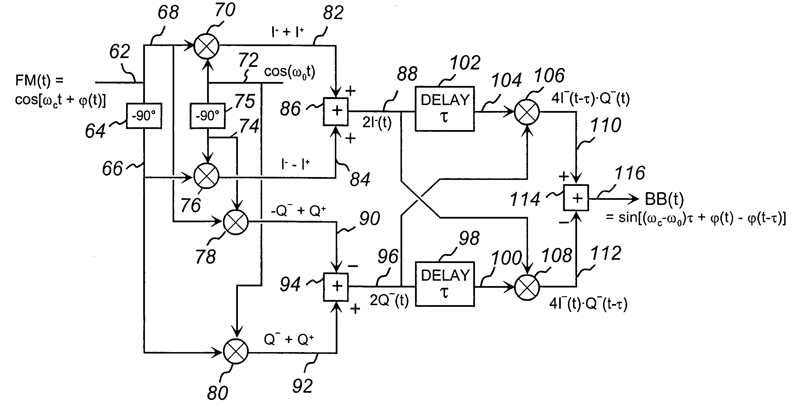
The present invention discloses a new type of extremely low-noise phase-frequency detector (PFD) 500, broadband from DC to multi-GHz RF frequencies for PLL synthesizer applications. Free of any feedback mechanisms, thus inherently fast, it operates close to transition frequency fT of IC processes or frequency limits of discrete mixers. The PFD 500 utilizes complex SSB conversion in both the in-phase and quadrature arms, delaying the in-phase arm in 530, beating the delayed signal 124 with the un-delayed quadrature signal 122 in mixer 126. The output 128 contains both the frequency difference and the phase difference information between the two signals 118 and 520, providing both the frequency-discrimination (FD) and the phase detection (PD) functions. Utilizing standard mixers the PFD 500 can achieve superior CNRs of 180 dBc / Hz at multi-GHz RF. Additionally, utilizing the FD / FM demodulation capability, the present invention improves phase noise of various signals and linearity of FM modulators.

Description

CROSS REFERENCE TO RELATED APPLICATIONS[0001]This application is a continuation-in-part of application Ser. No. 11 / 004,992, filed Dec. 7, 2004 now U.S. Pat. No. 6,982,592, allowed, which is a continuation of application Ser. No. 09 / 872,143, filed Jun. 1, 2001, now U.S. Pat. No. 6,847,255, the entire contents of which are hereby incorporated by reference.BACKGROUND OF THE INVENTION[0002]1. Field of the Invention[0003]This invention also relates to a new type of extremely low noise Phase / Frequency Discriminators / Detectors (PFD) providing significant advantages over prior art in frequency acquisition, phase locking / tracking and other applications, as well as FM demodulators employed in techniques for phase noise improvements of oscillators and other signals and sources and in highly linear FM modulators.[0004]2. Background of the Related Art[0005]Communication and other electronics systems use internally generated signals for various functions. Such signals are often generated by local...

Claims


Application Information

Patent Timeline
Patent Type & Authority Patents(United States)
IPC IPC(8): H04B1/18
CPCH03D3/007H03L7/085H03L7/087H03L7/113
Inventor PETROVIC, BRANISLAVASHKENASI, MAXIM
Owner ARRIS ENTERPRISES LLC
Learn More