
System and method for implementing a demand paging jitter buffer algorithm

a technology of demand paging and buffer algorithm, applied in the field of communication, can solve the problems of audio and/or video streaming across the communication network, diminishing the advantages of real-time communication, becoming unintelligible, etc., and achieve the effect of improving storage capacity and flexibility, reducing disadvantages and problems associated

Inactive Publication Date: 2008-05-06
CISCO TECH INC
View PDF11 Cites 6 Cited by
  • Summary
  • Abstract
  • Description
  • Claims
  • Application Information

AI Technical Summary

Benefits of technology

[0005]From the foregoing, it may be appreciated by those skilled in the art that a need has arisen for an improved processing approach that provides improved storage capacity and flexibility for a jitter buffer configuration. In accordance with one embodiment of the present invention, a system and a method for implementing a demand paging algorithm for a jitter buffer are provided that greatly reduce disadvantages and problems associated with conventional jitter buffer techniques.
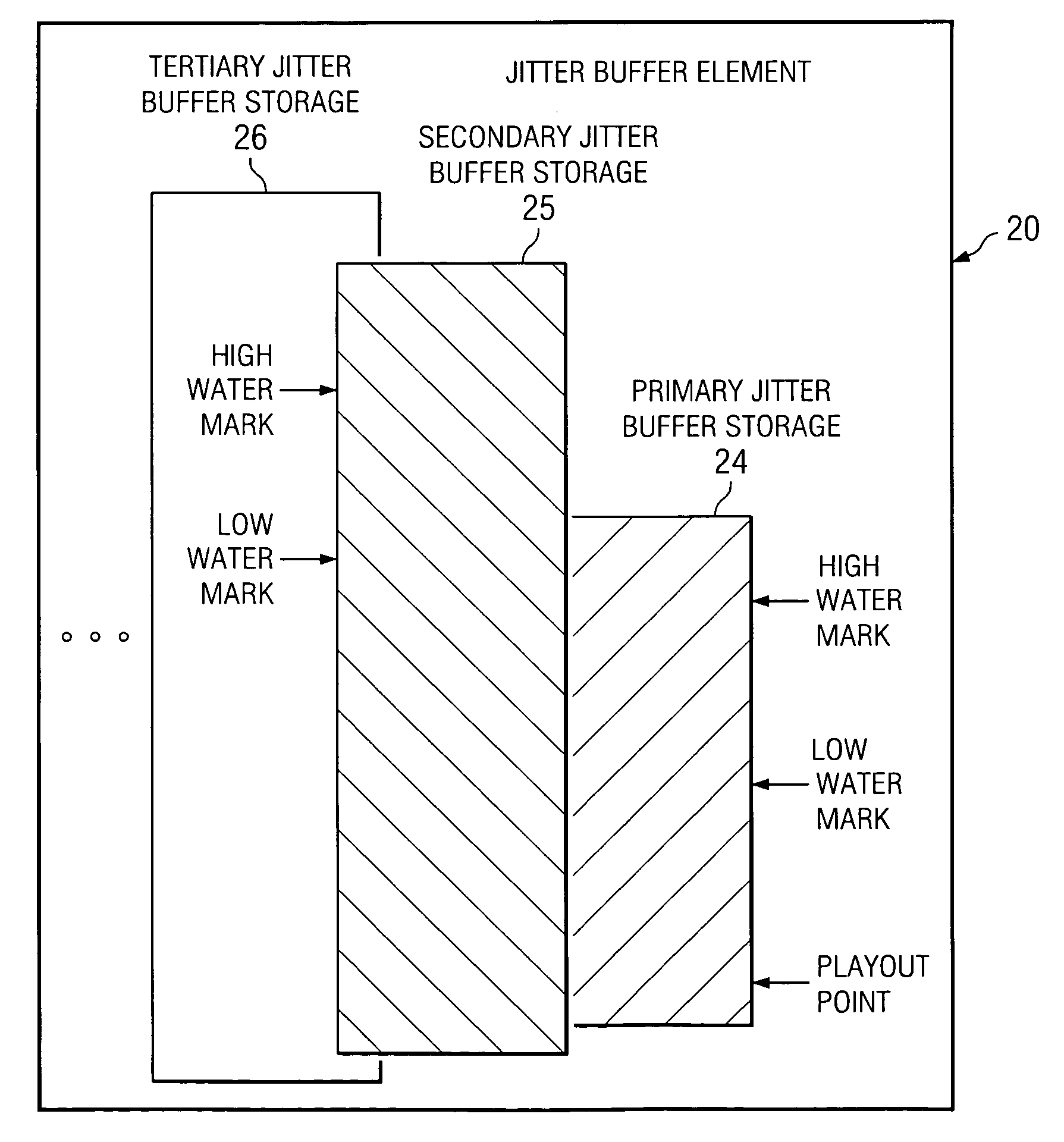
[0007]Certain embodiments of the present invention may provide a number of technical advantages. For example, according to one embodiment of the present invention, a jitter buffer configuration is provided that allows for the size of the jitter buffer to be extended indefinitely. This is a result of the unique architecture of the tendered jitter buffer, which includes multiple dependent jitter buffer segments that cooperate to achieve optimal storage parameters for an associated processor. In addition, because of the implementation of the proffered implementation, costs for various levels of memory can be successfully managed with less time-sensitive information being stored in less costly (higher order) memories. Only the most time-sensitive information need be kept in the most expensive memory. Hence, there is no need to keep the entire jitter buffer in the most expensive memory. This operates to free the expensive memory for other more beneficial uses for a given processor.
[0008]Another technical advantage associated with one embodiment of the present invention relates to flexibility. The configuration of the present invention, allows for an ability to accommodate large packets: even in memory-constrained processor architectures. This, in turn, yields optimal overhead for payload ratios. Moreover, the time required to service consumer / computer product controls (e.g. video cassette recorder (VCR) controls) can be minimized if the memory hierarchy contains the required speech.

Problems solved by technology

Audio and / or video streaming across a communication network may encounter delays that diminish the advantages of real-time communications.
Jitter is a variable-length delay that can cause a flow (e.g. a conversation) between two or more end points (e.g. two people) to break or to deteriorate and, thus, become unintelligible.
As a result of network congestion, improper queuing, or configuration errors, this steady stream can become fragmented: causing the delay between each packet to vary instead of remaining constant.
In VoIP networks in which existing data traffic might be bursty, jitter can be problematic.
This could inhibit the successful propagation of any type of real-time (or quasi real-time) communications.
Thus, the ability to properly manage real-time (or quasi real-time) communication flows presents a significant challenge to system designers, component manufacturers, and network operators.

Method used


Image

  • System and method for implementing a demand paging jitter buffer algorithm
  • System and method for implementing a demand paging jitter buffer algorithm
  • System and method for implementing a demand paging jitter buffer algorithm

Examples


Embodiment Construction

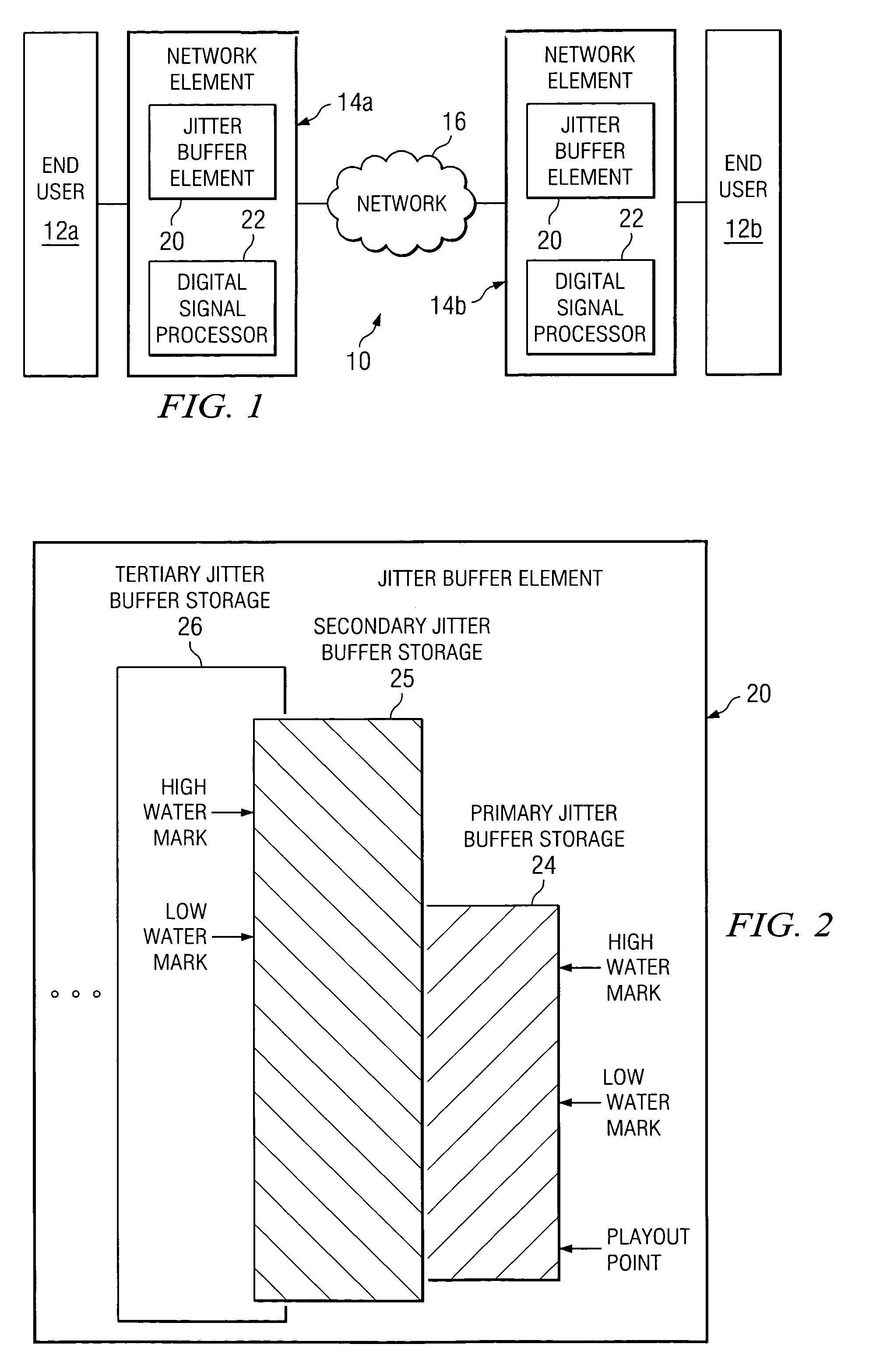
[0014]FIG. 1 is a simplified block diagram of a system 10 for communicating real-time data (or quasi or near real-time data) in a network environment. System 10 includes two end users 12a and 12b and two network elements 14a and 14b, which are coupled by an Internet protocol (IP) network 16. Within each network element 14a and 14b is a jitter buffer element 20 and a digital signal processor 22.

[0015]In accordance with the teachings of the present invention, system 10 provides an improved jitter buffer operation for any environment in which a jitter buffer operates. Jitter buffer elements 20 may perform all tasks associated with a traditional jitter buffer arrangement while offering several distinct enhancements that optimize communications and processing characteristics for system 10. System 10 models a jitter buffer in a demand paging scheme, which maximizes the value of hierarchies of memories. Additionally, such an approach allows for very large jitter buffer scenarios. Hence, th...


PUM


Abstract

An apparatus for providing storage is provided that includes a jitter buffer element. The jitter buffer element includes a primary jitter buffer storage that includes a primary low water mark and a primary high water mark. The jitter buffer element also includes a secondary jitter buffer storage that includes a secondary low water mark and a secondary high water mark. A first data segment within the primary jitter buffer storage is held for a processor. A playout point may advance from a bottom of the primary jitter buffer storage to the primary low water mark. When the playout point reaches the primary low water mark, the processor communicates a message for the secondary jitter buffer storage to request a second data segment up to the secondary high water mark associated with the secondary jitter buffer storage.

Description

TECHNICAL FIELD OF THE INVENTION[0001]This invention relates in general to the field of communications and, more particularly, to a system and a method for implementing a demand paging jitter buffer algorithm.BACKGROUND OF THE INVENTION[0002]Historically, telecommunications have involved the transmission of signals (e.g. voice) over a network dedicated to telecommunications, such as the public switched telephone network (PSTN) or a private branch exchange (PBX). Similarly, data communications between computers have also historically been transmitted on a dedicated data network, such as a local area network (LAN) or a wide area network (WAN), for example. Generally, telecommunications and data transmissions have been merged into an integrated communication network using technologies such as Voice over Internet Protocol (VoIP).[0003]Audio and / or video streaming across a communication network may encounter delays that diminish the advantages of real-time communications. Jitter is a var...

Claims


Application Information

Patent Timeline
Patent Type & Authority Patents(United States)
IPC IPC(8): G06F3/00G06F13/00
CPCG06F5/14
Inventor FITZGERALD, CARY W.
Owner CISCO TECH INC
Learn More