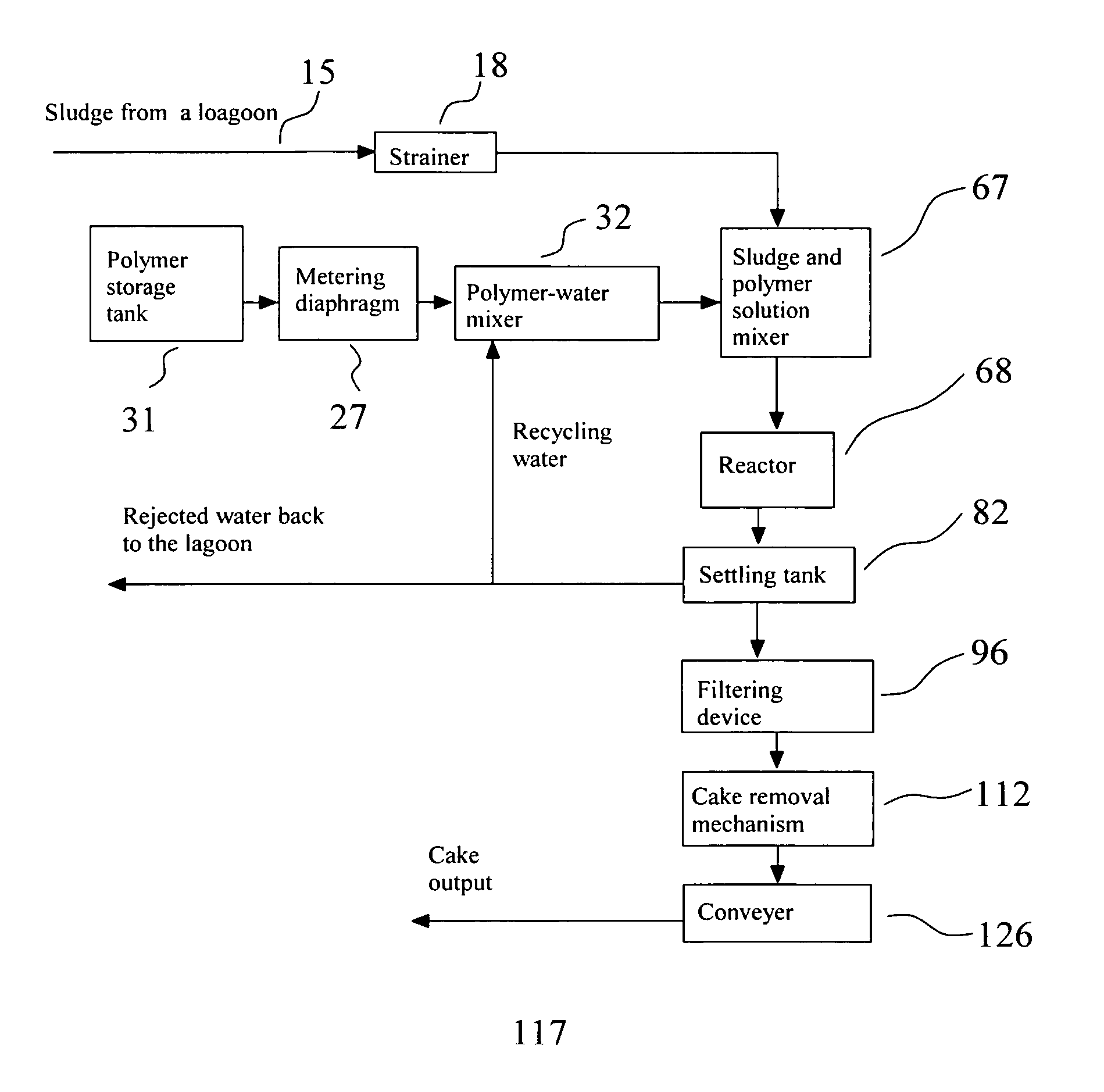
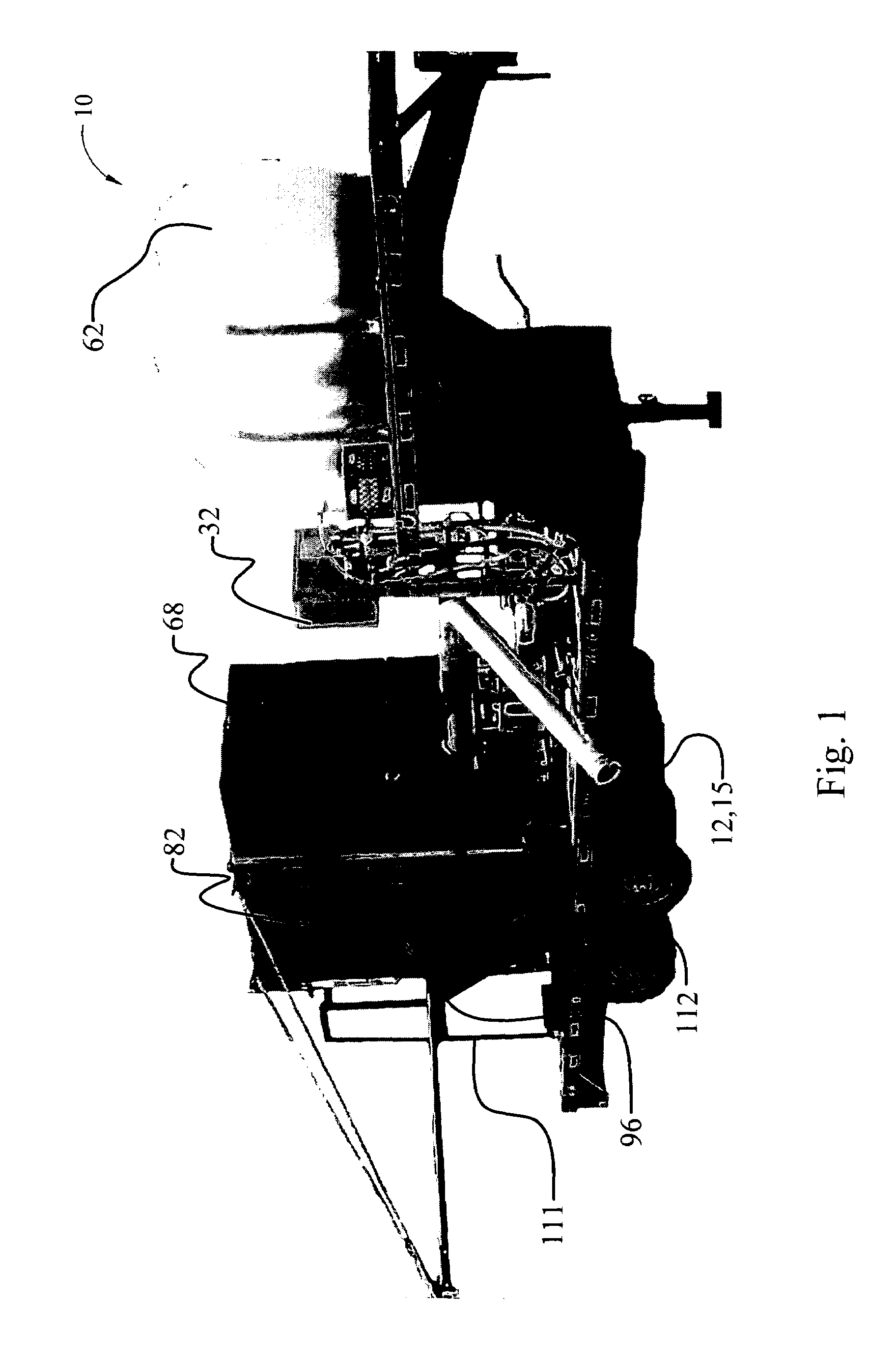
[0016]Accordingly, several objects and advantages of the invention are to provide an effective and deep
dehydration of liquid-
solid mixtures that obviates the disadvantages of prior separators. Specifically, the present art apparatus and method of use has a superior flow rate and volume ratio and provides deep
dewatering of sludge with high flow rates thus enabling it to be used in lagoons and other applications. The present art apparatus and method of use is a reliable device which requires minor, if any, maintenance and its production is simple and inexpensive compared with other separators of the same flow rate. New and unique elements of the present art which are substantially different from the prior art are a two-stage solving of a
polymer in the recycled or
reclaimed water, a reactor or
reaction chamber with two zones of
polymer / sludge interaction. The bottom zone is the incoming area of very intense turbulence where the polymer / sludge mixture completes the mixing process. This turbulent mixture goes through the lower laminator plates, which help make turbulence less violent to avoid tearing of clusters by shear stresses, but allow for further mixing. As the mix rises in the
reaction chamber, the chamber end walls (FIG. 15) widen. This increases the volume and further slows the turbulence. As the polymer / sludge mixture comes into the widest part of the
reaction chamber (FIG. 15), the flow passes through another set of laminator plates. These plates are arranged in two levels, one on the top of the other, in a 90 degree orientation to one another. If viewed from the top, they resemble a “
honeycomb”. After passing through the new and unique
honeycomb of laminator plates nearly all turbulence has subsided,
flocculation is nearly complete and
settling is starting to take place. In the reaction chamber, the upward movement of the flocculated mixture is greater than the
settling speed of the flocculated solids. Therefore, there is a net movement to the surface of the reaction chamber by the flocculated solids. The flocculated mixture now moves from the reaction chamber over a weir into the
settling chamber, where the surface area is 3.25 times greater than the surface area of the reaction chamber. In the
settling chamber, rapid settling of the flocculated solids takes place, this can approach 20 mm per second. Water separates at the upper water sludge interface at the top of the settling tank. Further new and unique elements are a grid of traps for water removal from the settling tank, one or more innovative filters which allow water to pass through while blocking solids, and deep de-watering via combined sedimentation and filtering.
[0017]As aforesaid, a grid of traps permits multi-level water rejection. That is, water separates from sludge at a number of vertically and horizontally arranged interfaces. The figures show a
schematic representation of preferably substantially inverse “V” shaped trap sets arranged inside the settling tank. Liquid separates from the solids in the traps within the settling tank. The
solid content of sludge increases downward, towards the bottom of the settling tank due to the aforesaid water separation. The traps increase the area of the water-sludge interface (where the rejection of water from sludge occurs) without increasing the volume of the settling tank. This makes the present art apparatus compact and efficient.
[0018]The number of trap
layers in the vertical direction must be properly chosen. That is, the sedimentation rate of solid particles decreases as the
solid content increases toward the bottom of the settling tank. For a concentration of solids to liquid greater than 40%, the sedimentation rate is typically so small that it is unreasonable to use the traps for sedimentation, and the sedimentation or solids removal process is replaced by
filtration. Thus, innovative filters are placed below said traps to further the liquid removal process and further enhance the deep
dehydration of the solids portion of the descending material (sludge).
[0019]The present art apparatus in at least one embodiment utilizes the aforesaid new and unique filters positioned below said traps, said filters comprising a plurality of uniquely shaped holes. Said filters geometrical features include but are not limited to hole / particle
diameter ratios, recesses, and proper distance /
diameter ratios in the hole arrangement to obtain optimum
filtration. The aforesaid, proper geometrical features are crucial for efficient filtration of liquid from the sludge at the solids concentrations stated and to further avoid solid particles from passing through said holes or blocking said filter holes. The unique hole geometry allows particles to form a kind of dome (as bricks form architectural domes) near each hole in the filter for more assured filtration. Spontaneous formation of said dome requires the aforesaid proper hole / particle
diameter ratios and dome resistance to flow disturbances requires said proper recesses and / or proper distance / diameter ratios to assure a sufficiently thick and robust dome buildup. Upon buildup, the dome structure substantially prohibits and blocks solid particles from transporting through the filter holes yet allows liquid or water to freely pass through both the domes and holes. This technique provides clean and efficient filtration, that is, clean separated water free of fine solid particles, without a continual necessity to frequently wash back the filter. In a preferred embodiment, the filtration rate is significantly increased when water suction is applied on the
water discharge side of said filters in addition to the
pressure action of the sludge head pressure.
[0021]In order to promote solids
flocculation, a flocculating agent such as a polymer is combined and mixed with the high
liquid content sludge. The present art utilizes a two stage solving technique of a flocculating agent with the recycling water in a preferred embodiment. That is, for preparation of the water-
polymer solution, the water rejected from the sludge (i.e., recycled water) can be used. Preparation of a water flocculating agent solution typically requires approximately 20 minutes for proper mixing. Conventional techniques therefore require that the solution must be prepared in advance and accumulated in a bulky
storage tank that can limit the transportability of the apparatus. The present art apparatus reduces the
storage tank size by at least ten times by using a two-stage flocculating agent solving process. In the first stage, one part of the flocculating agent concentrate, typically a polymer, and ninety nine parts of water are mixed for 20 minutes, resulting in a 1 / 100 polymer / water solution. In the second stage, one part of the prepared solution and 9 parts of water, are mixed for 3 seconds, resulting in a 1 / 1000 flocculating agent / water solution. Finally, 4 parts of the 1 / 1000 solution and 96 parts of the sludge are mixed, resulting in 40 parts per million (ppm) flocculating agent / sludge mixture. This final mixture with the flocculated
solid content is directed to the reaction chamber, where flocculation occurs, to the
settling chamber, where sedimentation occurs, and next to the filters, where deep dehydration occurs. This two stage solving and mixing process drastically reduces the storage-tank volume required.
[0022]The present art provides an efficient mixing of the incoming sludge with a polymer-water solution, suppression of turbulent pulsations and deceleration of the
mixed flow in the reactor in order to provide proper conditions for
solid particle flocculation by the flocculating agent into large clusters, a quiet flow near the top of the reactor and settling tanks that provides efficient separation of “easy” liquid or water from the sludge, a grid of traps within the settling chamber which provides efficient water rejection from the bulk mix within the settling tank, and additional filter rejection of liquid or water from the sludge. The final unique
filtration technique of the process transforms the flocculated agent-sludge mixture into a paste and then into a cake which can be discharged.


