
Semiconductor laser device and method for fabricating the same

a laser device and semiconductor technology, applied in the field of semiconductor laser devices, can solve the problems of deterioration of temperature characteristics of semiconductor devices, insufficient output, and degraded reliability of semiconductor devices, and achieve the effect of high output operation

Inactive Publication Date: 2007-05-08
PANASONIC CORP
View PDF24 Cites 2 Cited by
  • Summary
  • Abstract
  • Description
  • Claims
  • Application Information

AI Technical Summary

Benefits of technology

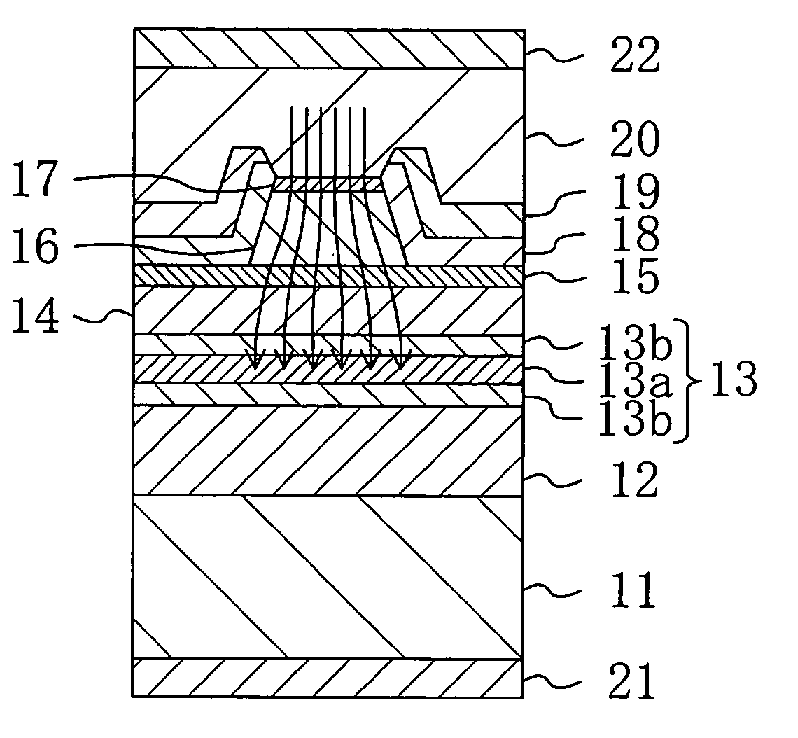
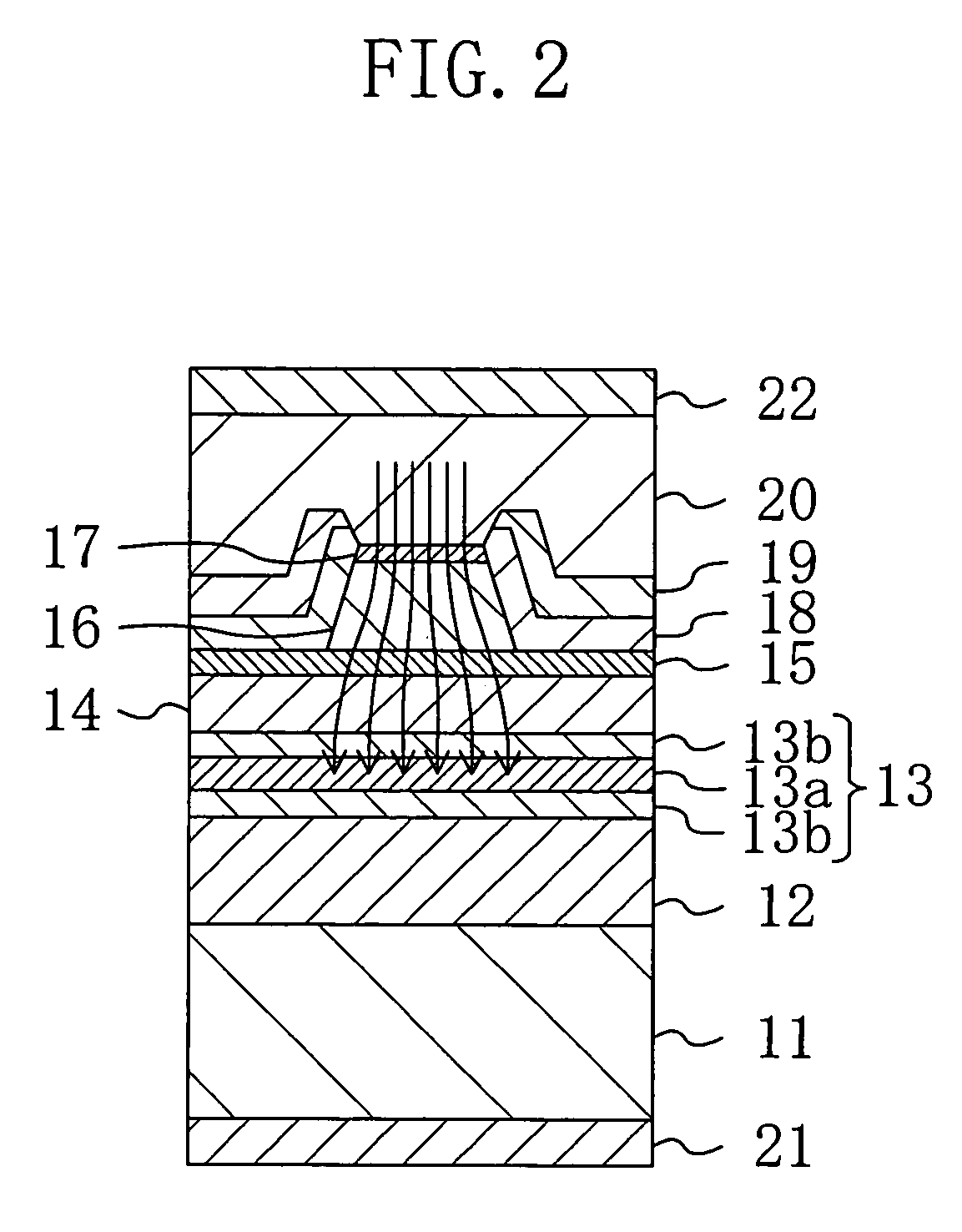
[0015]It is therefore an object of the present invention to solve the foregoing conventional problems and thereby enabling a semiconductor laser device to perform a high-output operation by reducing an ineffective current resulting from the diffusion of a current in a cladding layer.

Problems solved by technology

The overflow of electrons reduces a threshold current and an operating current so that a sufficient output is not obtained.
If the first p-type cladding layer 104 is heavily doped with a p-type impurity, however, the p-type impurity is diffused into the active layer 103 to form a nonradiative recombination center so that the temperature characteristic of the semiconductor device deteriorates and the reliability thereof is degraded.
Thus, the conventional semiconductor laser device described above has a problem that a high output cannot be obtained therefrom because ineffective currents resulting from the diffusion of currents in the cladding layer formed on the active layer reduce a luminous efficiency and increase a threshold current as well as an operating current.

Method used


Image

  • Semiconductor laser device and method for fabricating the same
  • Semiconductor laser device and method for fabricating the same
  • Semiconductor laser device and method for fabricating the same

Examples


embodiment 1

Variation 2 of Embodiment 1

[0109]A semiconductor laser device according to a second variation of the first embodiment will be described herein below with reference to the drawings.

[0110]FIG. 6 shows a cross-sectional structure of the semiconductor laser device according to the second variation of the first embodiment. The description of the components shown in FIG. 6 which are the same as those shown in FIG. 1 will be omitted by retaining the same reference numerals.

[0111]As shown in FIG. 6, the n-type cladding layer 12, the active layer 13 having a multiple quantum well structure, the first p-type cladding layer 14, and the etching stopper layer 15 are deposited successively by crystal growth on the n-type substrate 11. A current blocking layer 41 made of n-type Al0.5In0.5P with a film thickness of about 0.3 μm and formed with a stripe trench portion and a second p-type cladding layer 42 made of p-type Al0.35G0.15In0.5P with a film thickness of about 2 μm and having a lower portion...

embodiment 2

[0116]The second embodiment of the present invention will be described herein below with reference to the drawings.

[0117]FIG. 7 shows a cross-sectional structure of the semiconductor laser device according to the second embodiment. The description of the components shown in FIG. 7 which are the same as shown in FIG. 1 will be omitted by retaining the same reference numerals.

[0118]As shown in FIG. 7, an n-type cladding layer 52 made of n-type Al0.5Ga0.5As with a thickness of about 2.5 μm, an active layer 53 having a multiple quantum well structure, a first p-type cladding layer 54 made of p-type Al0.5Ga0.5As with a film thickness of about 0.1 μm, an etching stopper layer 55 made of p-type Al0.2Ga0.8As with a film thickness of about 10 nm, and a second p-type cladding layer 56 made of p-type Al0.5Ga0.5As with a film thickness of about 1 μm and formed into a ridge-shaped configuration are deposited successively by crystal growth on an n-type substrate 51 made of n-type GaAs with a thic...


PUM

PropertyMeasurementUnit
wavelengthaaaaaaaaaa
thicknessaaaaaaaaaa
thicknessaaaaaaaaaa

Abstract

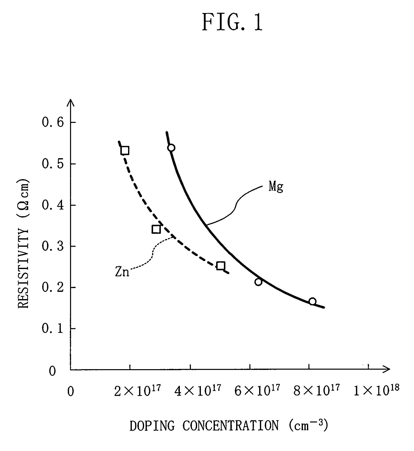
A semiconductor laser device has an active layer, a first cladding layer formed on the active layer, and a second cladding layer formed on the first cladding layer. The first cladding layer is doped with magnesium as a first impurity to have a high resistivity. The second cladding layer is doped with zinc as a second impurity to have a resistivity lower than the resistivity of the first cladding layer.

Description

BACKGROUND OF THE INVENTION[0001]The present invention relates to a semiconductor laser device composed of a group III–V compound semiconductor and, more particularly, to a semiconductor laser device capable of a high-output and low-voltage operation and to a method for fabricating the same.[0002]Because of their ability to record information at an extremely high density, digital versatile disk (DVD) devices have achieved rapid widespread use in the fields of personal computers and audio-video equipment. In particular, growing expectations have been placed on further proliferation of writable or rewritable DVD devices as, e.g., external large-capacity memory devices (such as so-called DVD-R and DVD-RAM) or as next-generation video recorders (so-called DVD recorders) which are replacements for video tape recorders.[0003]As a pick-up light source used in such a writable or rewritable DVD device to enable reading or rewriting of data, a semiconductor laser device which emits a red ligh...

Claims


Application Information

Patent Timeline
Patent Type & Authority Patents(United States)
IPC IPC(8): H01S5/00H01S5/22H01S5/223H01S5/30H01S5/343
CPCB82Y20/00H01S5/2231H01S5/305H01S5/34326H01S5/2206H01S5/3054H01S5/3436
Inventor ONISHI, TOSHIKAZU
Owner PANASONIC CORP
Learn More