
Semiconductor laser device and method for fabricating the same

a laser device and semiconductor technology, applied in the direction of laser optical resonator construction, laser details, nanooptics, etc., can solve the problems of inability to provide a sufficiently large band barrier against electrons in the conduction band, inability to ignore the influence of solid-phase diffusion in algainp-based materials, etc., to achieve high reliability

Inactive Publication Date: 2008-07-22
PANASONIC CORP
View PDF26 Cites 0 Cited by
  • Summary
  • Abstract
  • Description
  • Claims
  • Application Information

AI Technical Summary

Benefits of technology

"The present invention provides a semiconductor laser device that can operate at high temperature with high reliability. By using a dopant diffusion preventing layer containing arsenic between the clad layer and the active layer, the device can achieve high-output operation with high-concentration doping of the clad layer. The use of a guide layer between the dopant diffusion preventing layer and the active layer further prevents interdiffusion of phosphorus and arsenic, resulting in a semiconductor laser device with reduced power consumption and improved beam quality. The invention also provides a method for fabricating the semiconductor laser device."

Problems solved by technology

If a semiconductor laser device is increased in output, however, the problem is encountered that the output thereof is saturated.
The problem is conspicuous when the semiconductor laser device is operating at a high temperature.
This is because an AlGaInP-based material composing the p-type clad layer of the red laser has a limitation in that it cannot provide a sufficiently large band barrier against electrons in the conduction band.
However, the influence of solid-phase diffusion cannot be ignored in the AlGaInP-based material because of the diffusion coefficient of the p-type impurity which is generally high therein.
The production of a crystal defect reduces the lifespan of the semiconductor laser.
Due to the impurity diffusion in the active layer described above, the doping of the p-type clad layer with the p-type impurity at a high concentration has been difficult.
As the thickness of the spacer layer is increased, however, a series resistance is increased so that an operating current is increased disadvantageously or it becomes difficult to obtain a desired beam configuration under the influence of the spacer layer.

Method used


Image

  • Semiconductor laser device and method for fabricating the same
  • Semiconductor laser device and method for fabricating the same
  • Semiconductor laser device and method for fabricating the same

Examples


embodiment 1

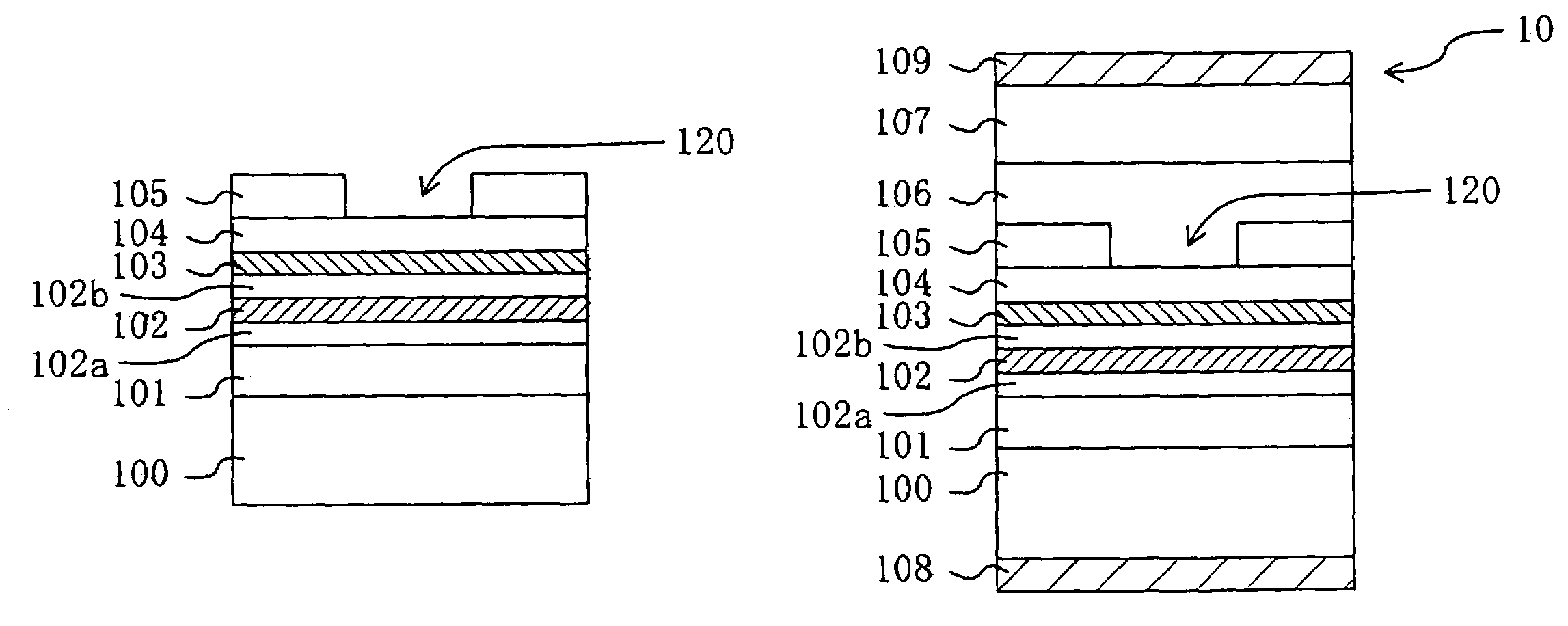
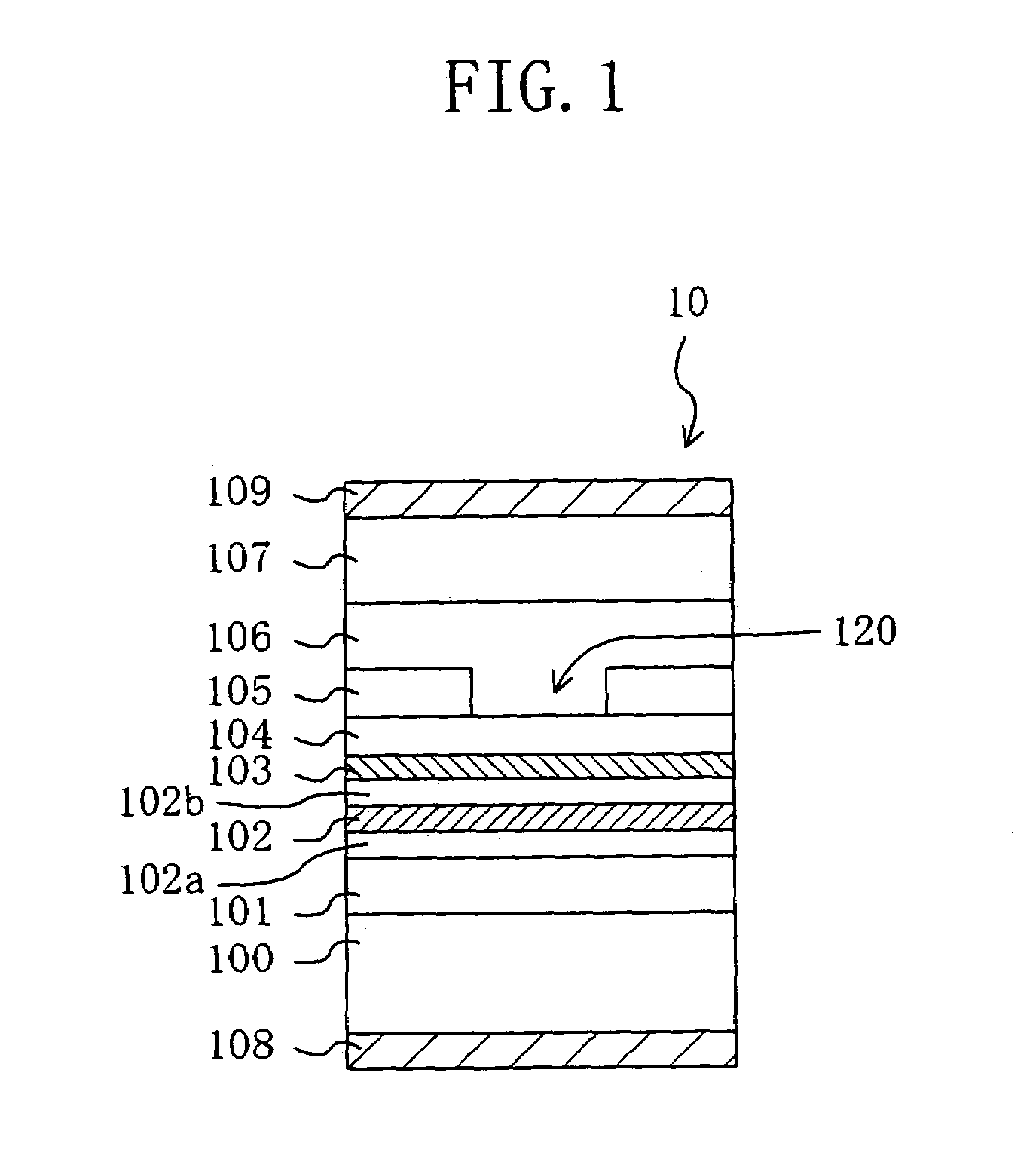
[0047]FIG. 1 is a cross-sectional view of a semiconductor laser-device according to EMBODIMENT 1 of the present invention.

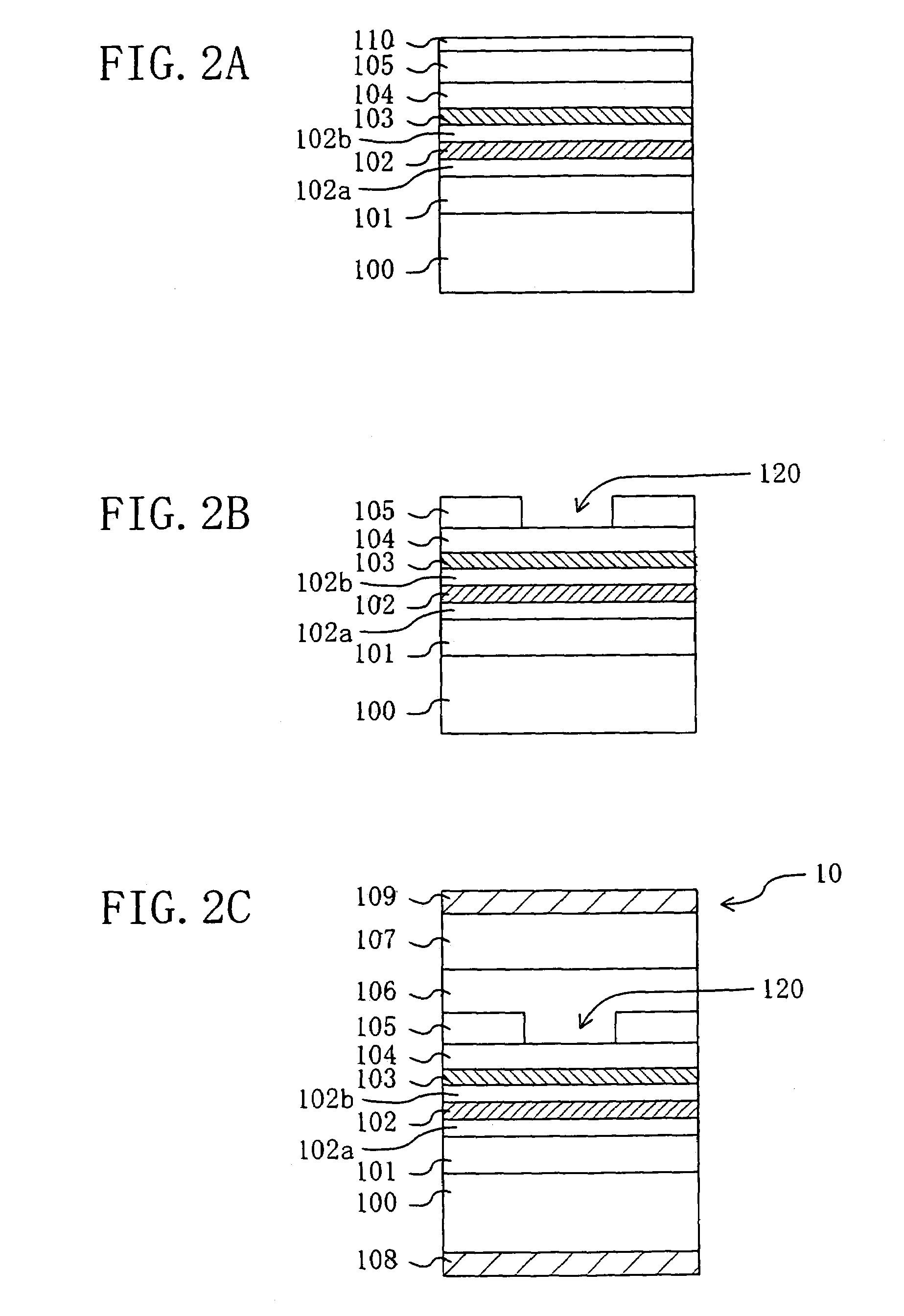
[0048]As shown in FIG. 1, a semiconductor laser device 10 according to the present embodiment has a multilayer structure composed of: an n-type clad layer 101 made of n-type AlGaInP; a guide layer 102a (with a thickness of 30 nm) made of AlGaInP; an active layer 102 composed of a quantum well consisting of a plurality of GaInP layers and a plurality of AlGaInP layers; a guide layer 102b (with a thickness of 30 nm) made of AlGaInP; a diffusion preventing layer 103 made of AlGaAs; a first p-type clad layer 104 made of p-type AlGaInP; a current block layer 105 made of n-type AlGaInP; a second p-type clad layer 106 made of p-type AlGaInP; and a contact layer 107 made of p-type GaAs, which are stacked successively on a substrate 100 made of n-type GaAs.

[0049]In the present embodiment, the active layer 102 is composed of a repetition of the structure in which the GaInP...

embodiment 2

[0085]FIG. 5 is a cross-sectional view of a semiconductor laser device according to EMBODIMENT 2 of the present invention.

[0086]As shown in FIG. 5, a semiconductor laser device 50 according to the present embodiment has a multilayer structure composed of: an n-type clad layer 101 made of n-type AlGaInP; a guide layer 102a (with a thickness of 30 nm) made of AlGaInP; an active layer 102 composed of a quantum well consisting of a plurality of GaInP layers and a plurality of AlGaInP layers; a guide layer 102b (with a thickness of 30 nm) made of AlGaInP; a diffusion preventing layer 103 made of AlGaAs; a first p-type clad layer 104 made of p-type AlGaInP; an etching stop layer 130 made of GaInP; a current block layer 105 made of n-type AlGaInP; a second p-type clad layer 106 made of p-type AlGaInP; and a contact layer 107 made of p-type GaAs, which are stacked successively on a substrate 100 made of n-type GaAs.

[0087]In the present embodiment, the active layer 102 is composed of a repet...

embodiment 3

[0107]FIG. 8 is a perspective view showing a structure of a semiconductor laser device according to EMBODIMENT 3.

[0108]As shown in FIG. 8, a semiconductor laser device 80 according to the present embodiment has a structure (so-called window structure) comprising laser facet regions 112 and an internal region 113.

[0109]Each of the laser facet regions 112 has a multilayer structure composed of: an n-type clad layer 101 made of n-type AlGaInP; a guide layer 102a (with a thickness of 30 nm) made of AlGaInP; an alloyed active layer 111 made of alloyed GaInP and AlGaInP; a guide layer 102b (with a thickness of 30 nm) made of AlGaInP; a first p-type clad layer 104 made of p-type AlGaInP; an etching stop layer 130 made of GaInP; a current block layer 105 made of n-type AlGaInP; a second p-type clad layer 106 made of p-type AlGaInP; and a contact layer 107 made of p-type GaAs, which are stacked successively on a substrate 100 made of n-type GaAs.

[0110]The internal region 113 has a multilayer...


PUM


Abstract

A semiconductor laser device according to the present invention has a semiconductor substrate, an active layer formed on the semiconductor substrate and made of a compound semiconductor containing phosphorus, a guide layer formed on the active layer and made of a compound semiconductor a dopant diffusion preventing layer formed on the guide layer and made of a semiconductor compound containing arsenic, and a clad layer formed on the dopant diffusion preventing layer and made of a compound semiconductor containing a dopant.

Description

BACKGROUND OF THE INVENTION[0001]The present invention relates to a semiconductor laser device and to a method for fabricating the same. More particularly, it relates to an increase in the output of the semiconductor laser device.[0002]Recent years have seen rapid widespread use of DVD (Digital Versatile Disk) devices in the fields of AV (Audio-Video) equipment, PCs (Personal Computers), and the like. In particular, great expectations have been placed on the use of recordable DVD devices (such as DVD-RAM and DVD-R) as large-capacity memory devices embedded in PCs and the like and as post-VTR (Video Tape Recorder) devices.[0003]As pickup light sources for the foregoing DVD devices, red semiconductor lasers at wavelengths in the 650 nm band have been used. With the recent increases in the density and capacity of an optical disk, a pick-up light source capable of performing a particularly high output operation over 80 mW has been in growing demand to allow a higher-speed write operatio...

Claims


Application Information

Patent Timeline
Patent Type & Authority Patents(United States)
IPC IPC(8): H01L21/00H01S5/16H01S5/223H01S5/343
CPCB82Y20/00H01S5/164H01S5/2231H01S5/3436H01S5/3072H01S5/34326
Inventor ONISHI, TOSHIKAZU
Owner PANASONIC CORP
Learn More