
Softclip method and apparatus

a softclip and apparatus technology, applied in the direction of volume compression/expansion having semiconductor devices, volume compression/expansion in untuned/low-frequency amplifiers, instruments, etc., to achieve the effect of cost-effectiveness

Inactive Publication Date: 2007-04-17
SYFX
View PDF6 Cites 22 Cited by
  • Summary
  • Abstract
  • Description
  • Claims
  • Application Information

AI Technical Summary

Benefits of technology

[0045]The partitioned signal processing system and method of the present invention substantially overcomes each of the aforementioned limitations of the prior art. Because of the substantial flexibility of the system and method of the present invention, cost effective implementations may be envisioned which range from alarms, ringers and phones, to car stereos and home entertainment systems, to recording studios and theaters, and to applications distributed across a network. In addition, the system and method are capable of use in other non-audio signal processing applications. A feature of many implementations of the invention is that substantially arbitrary, dynamic, and flexible processing throughout an environment becomes possible. The architecture of the present invention permits both digital and analog implementations, and also permits partitioning of both hardware and software. Moreover, modules can be concentrated locally, or dispersed across a network which may include communications links. In at least some embodiments it may be desirable to permit reconfiguration of the modules; this can be accomplished either through software such as dynamic switching or packet routing, or through hardware such as crossbar switches or remote controls.
[0048]Input Signal Preprocessor—The input signal preprocessor allows a multitude of input signals to be multiplexed, synchronization of asynchronous events and data, and other signal processing such as analog to digital data conversion, bandsplit filtering and equalization, and input level adjusting to be performed. The input level adjust function adjusts the peak input signal (largest amplitude input signal) supplied by the selected source to the 0-dB level (largest amplitude signal) allowed by subsequent processing modules and allows for optimum compander operation. Bandsplit filtering and equalization allows dividing a signal into a multitude of frequency bands, and then performing equalization on each frequency band as required and allows for multiband signal processing.
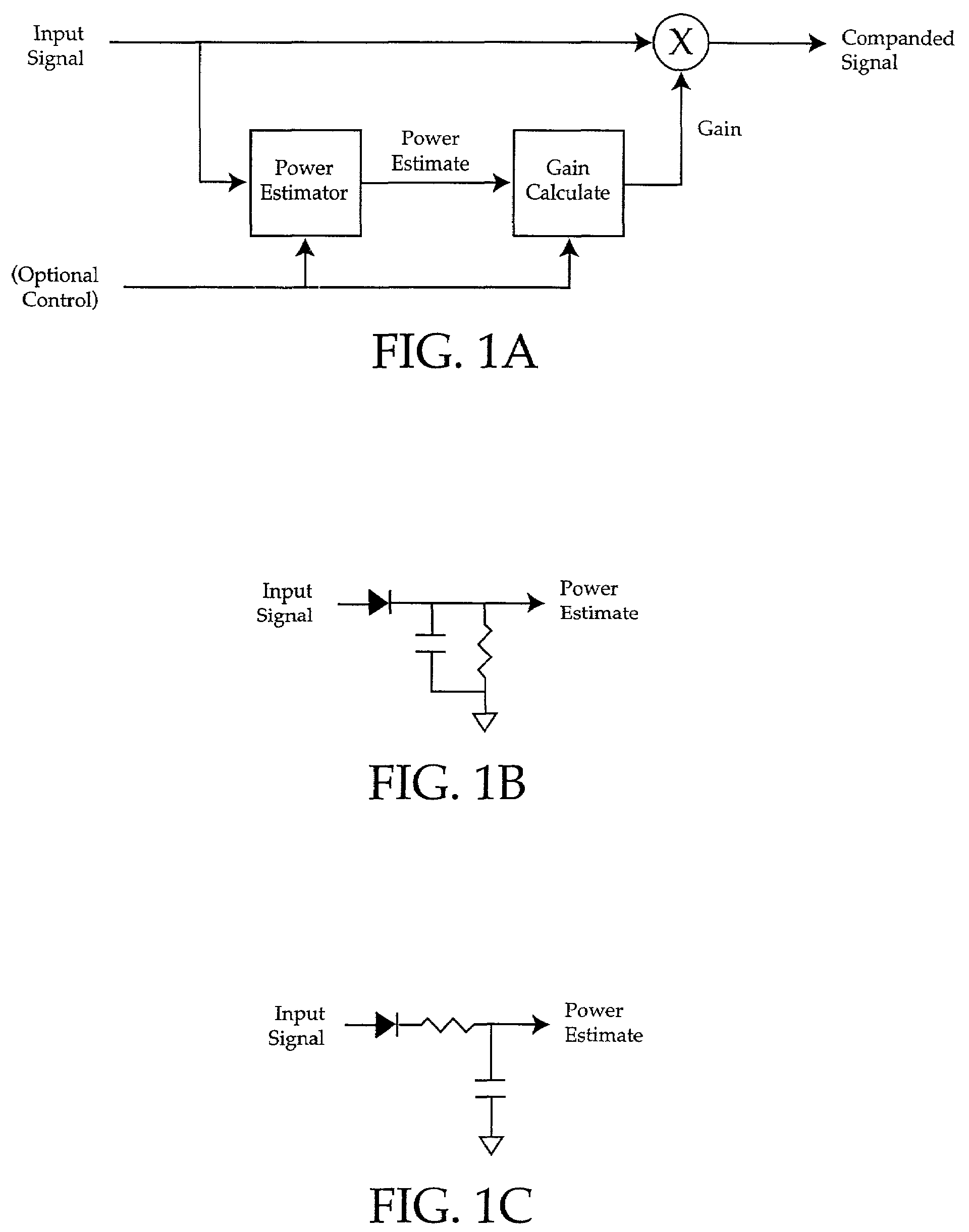
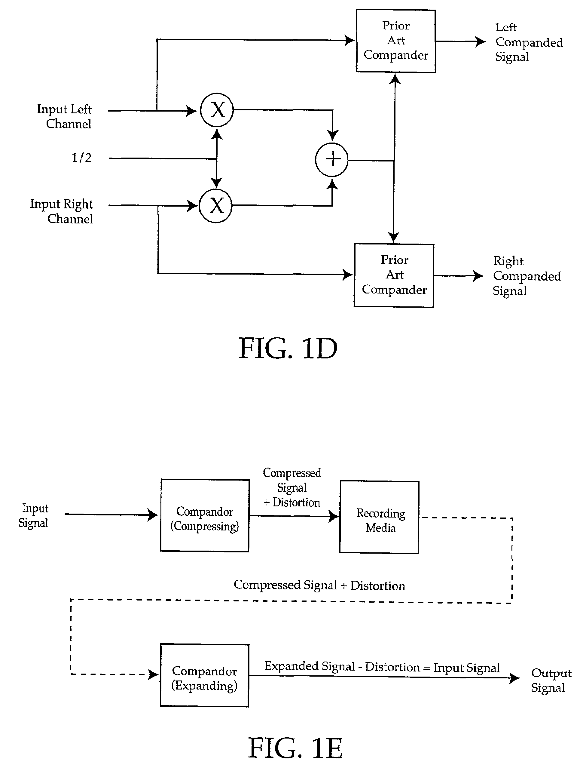
[0049]Adaptive Dynamic Compander—The Adaptive Dynamic Compander allows extremely low signal distortion, wide bandwidth, dynamic range mapping by matching the input source dynamic range to the listener's dynamic range by either compressing or expanding an input signal. Extremely low distortion is provided by the half-wave signal processor which causes changes in gain only at zero crossings to minimize signal distortion. The half-wave signal processor may also include an optional synchronizer to insure that the calculated gain is used on the correct half-cycle, leading to improved transient response, a variable attack and release feature (also used in other modules) to dynamically modify the compander response time to varying input levels, a post-power estimator mixer that allows multiple companders to be used in multiple channel / band configurations, without altering relative spatial information or causing signal distortion, and a gain calculator for determining the amount of instantaneous gain by which a signal should be multiplied to be correctly companded. Many audio signals consist of a plurality of channels used to provide stereo or theater sound reproduction. When companding audio signals, it is desirable to preserve the relative amplitudes of the channels to each other, to preserve spatial location information. Using a post-power estimator mixer in each compander or in a centralized power estimator mixer, allows uniform changes to be made on all channels, preserving spatial signal intensity information, and minimizing inter-channel / band distortions and clipping. The gain calculator may include a look-ahead output clip detector for minimizing output signal clipping distortion for signals changing faster than the reaction time of the adaptive dynamic compander. Alternatively, a soft clip function may be used for minimizing output signal clipping distortion.
[0050]Central Post Power Estimator Mixer—Use of a Central Post Power Estimator Mixer reduces processing requirements and allows multiple companders to be used in multiple channel / band configurations without altering relative spatial information or causing signal distortion or clipping.
[0051]Volume Control and Pre-Mixer—The Volume Control and Pre-Mixer selects either input signals or a calibration signal to be output and allows the user to make fine adjustments of the output signal amplitude. A pre-mix function allows a multitude of input signals, typically multiple frequency bands or channels, to be combined into a given volume control.

Problems solved by technology

Existing audio signal processing systems suffer from a variety of limitations.
Some of the limitations are imposed by the transmission or storage medium or other technological deficiencies; other limitations are the result of environmental issues.
For example, the amplification necessary to hear the quietest portions of an audio signal may result in maximum amplitudes that are undesirably loud.
Conversely, amplitudes allowing loud portions of an audio signal to be heard at a comfortable level, may result in not being able to hear quiet portions of the signal.
Peak detectors and low pass filters suffer from increasing low frequency distortion as the signal frequency approaches the corner frequency of the circuits.
Lowering the corner frequency to decrease the low frequency distortion increases the transient response time leading to overamplification and signal clipping and underamplification.
Dividing the total bandwidth into multiple frequency bands and using multiple companders can reduce distortion and transient response time but at the cost of the extra processing for the additional companders.
The input signal mixing typically results in additional distortion since the adjacent channel signal is partly controlling the compander gain.
It also typically results in one channel being under-amplified and the other channel being over-amplified which can result in clipping distortion.
Broadcast or recording restrictions or other technological limitations often mandate that the maximum amplitude range of a signal be restricted, and as a result signals are compressed to remain within those restrictions and limitations.
Thus a compressor and expander pair can be used to cancel out low frequency distortion, but do not and cannot function as a standalone compressor or expander.
One common limitation of prior art audio signal processing systems is that it is often difficult for a listener to comfortably hear all portions of an audio signal due to environmental audio noise.
Environmental noise is transient and often unpredictable in nature, which makes manual adjustment to compensate for it particularly difficult.
If the user manually increases the volume for times when the signal cannot be heard due to loud transient noise, the volume will be too loud once when the noise has subsided or the audio signal becomes greater in amplitude.
This problem occurs in many situations, usually (though not always) involving outdoors or mobile environments such as a car stereo, a cellular telephone used in public places, a portable radio used during a public sporting event, or home theater systems.
This type of prior art solutions provides no means of calibration of the circuitry to the acoustic environment making their proper operation unpredictable.
They also do not satisfactorily address problems with variations in the audio source such as long silent pauses in the audio signal, uncontrolled positive feedback known as gain chase, room acoustic resonances that appear as false noise, or allow changing the minimum signal to noise ratio of the system.
Further, they have an inadequate response to noise in that some respond too quickly, reacting to phone ringers and short bursts of speech, while others have too long and inaccurate a response.
Prior art solutions also do not allow the user to select the signal or noise priority so that if the noise is speech, the signal source will be reduced instead of increased.
The signal necessary to provide adequate sound in one location, often results in sounds that are either too loud or quiet in other areas.
Prior art solutions have no automatic adjustments and require manual adjustments with little or no explanation.
While this technique will work for any particular frequency, it is not able to maintain a 90-degree separation over all frequencies.Beard U.S. Pat. No. 4,169,219 (1979) teaches the use of an analog, low-pass-filter delay-buffer in implementing a compressor-expansion pair, for recording a compressed signal that subsequently would be expanded upon being played.
It is unsuitable for standalone use due to significant distortion of low frequency signals.Bethards U.S. Pat. No. 4,216,427 (1980) instructs in the use of an adaptive audio compressor using analog techniques for restricting subsequent RF signal modulation.
This technique provides unacceptable distortion of wide band audio signals.Unagami et al.
Its use of a low-pass filter results in high distortion at low frequencies, and its overall design causes undesirable signal clipping.Rosback U.S. Pat. No. 4,641,361 (1987) instructs in the use of an analog, multi-frequency band, automatic gain circuit that makes use of a peak clipper to reduce overall gain.
Gain is changed continuously, resulting in distortion at low frequencies.Bloy et al.
This technique undesirably amplifies the signal noise floor.
It is a complex design that uses both analog and digital circuitry.
Changes in gain are made continuously, resulting in inherent signal distortion.U.S. Pat. No. 4,322,579 to Kleis et al.
The primary disadvantage of this invention is that it suffers from positive feedback between the speaker and microphone, making it only useful for headphone applications.
It has the disadvantage that it always amplifies the signal, when compressing the signal would provide superior comfort to the user.
The difficulty with this patent is that it requires that the microphone only detect noise, and thus places it in a vehicle engine compartment, when in fact, wind noise is often the dominant source of environmental noise, resulting in the circuit not solving the stated problem.U.S. Pat. No. 4,882,762 to Waldhaner (1989) teaches the use of a programmable multi-band compression system for hearing aids.
It does not provide variable, automatic compensation of the signal in the presence of environmental noise, since it has no way to detect or distinguish this noise.U.S. Pat. No. 4,891,837 to Walker et al.
The disadvantage of this technique is that a sample and hold circuit must be used to avoid a noise problem whenever the audio input signal goes silent.U.S. Pat. No. 5,107,539 to Kato et al.
This circuit has several disadvantages, long silent pauses in the audio signal will result in undesirably loud amplification, and it does no compression of the signal, resulting in situations where the audio signal becomes too loud.U.S. Pat. No. 5,172,358 to Kimura (1992) shows the usage of a digital signal processor to boost low and high frequencies depending on the average amount of sound pressure.
No means are provided to calibrate the actual sound pressure with the levels inside the circuit.
Adaptive and least means square algorithms are computationally intensive and in certain situations can add undesirable amounts of distortion to a signal.
No signal companding is performed, resulting in circumstances where certain noise-dominant frequency bands are amplified painfully loud.
The main distinctive feature is the use of a delay line that is ineffective due to room reverberation and variations caused by changing microphone position.
This method works for fixed delays, but does not function well in situations where there is considerable phase delay, signal dispersion or echoes.
No signal companding is performed, resulting in circumstances where the output volume is unacceptably loud.
It does not address normal mode resonances due to room acoustics providing incorrect calibration.U.S. Pat. No. 4,558,460 to Tanaka, et al.
This will not work in a non-automotive setting since the noise compensation is dependent on vehicle speed and not environmental noise.
All produce high levels of signal distortion at low frequencies.
Using multiple frequency band compander techniques to reduce distortion requires significant additional processing requirements.
Many rely upon a compressor and expander pair to cancel out low frequency distortion, and do not and cannot function as a standalone compressor or expander.
Many of the companders are implemented using analog designs that do not address considerations necessary for the use of digital signal processors, or take advantage of their capabilities.
Some use multiple channel compander designs with input signal mixing that result in inter-channel modulation distortion and output clipping.
Most compander designs use fixed attack and release times or use a plurality of fixed attack and release time-constant filters, that can result in additional signal distortion or limited operating range.
Further, prior art noise compensators suffer from gain chase problems, inadequate and inaccurate response to noise, a lack of signal or noise priority choice, and no means to vary the output signal to noise ratio.
Prior art systems typically require redundant equipment and do not provide automatic adjustments.
In summary, existing inventions are ineffective due to inherent design limitations.

Method used


Image

  • Softclip method and apparatus
  • Softclip method and apparatus
  • Softclip method and apparatus

Examples


Embodiment Construction

[0220]Referring next to FIGS. 3A and 3B, numerous aspects of the overall system and process flow of the present invention can be appreciated at least generally. With particular reference to FIG. 3A, the system 300 can be seen, in broadest form, to comprise a plurality of user interface and signal processor configurator blocks 305A-n combined which receives user control signals 310 as inputs, including bidirectional remote links 310A, and communicates bidirectionally with signal processor blocks 315A-o. Aside from the signals communicated by the user interface block 305 to the signal processor block 315, the user interface block 305 also provides user display signals 320. The signal processor blocks 315A-o receive additional signal inputs 325, which may come from any of a variety of audio or similar sources, and generated one or more signal outputs 330 which have been expanded, compressed, or otherwise modified in accordance with features described in greater detail hereinafter.

[0221...


PUM


Abstract

A method of matching input amplitudes in a system wherein one or more of a plurality of inputs may be selected, with each input capable of having different characteristics, involving selecting an input signal and mapping the input signal to a predetermined signal amplitude through the use of level matching logic. The level matching logic may include a gain cell for increasing or decreasing the amplitude of the input signal.

Description

RELATED APPLICATION[0001]This application is related to Provisional U.S. Patent Application No. 60 / 167,944, filed Nov. 29, 1999, and Provisional U.S. Patent Application No. 60 / 236,397, filed Sep. 28, 2000, entitled PARTITIONED SIGNAL PROCESSING SYSTEM WITH AUTOMATIC NOISE COMPENSATION AND METHOD, and having the same inventors as the present application.FIELD OF THE INVENTION[0002]This invention relates to the art of distributed signal processing systems that may include companders, noise compensators, and methods of controlling systems that include companders, volume controls and noise compensators.BACKGROUND OF THE INVENTION[0003]Existing audio signal processing systems suffer from a variety of limitations. Some of the limitations are imposed by the transmission or storage medium or other technological deficiencies; other limitations are the result of environmental issues. Regardless of the reason, the result is the same: the listener receives a less than optimal listening experien...

Claims


Application Information

Patent Timeline
Patent Type & Authority Patents(United States)
IPC IPC(8): H03G7/00G10L21/02H03G3/30H03G3/32H03G7/06H03G9/02H04R3/00H04R25/00H04R27/00
CPCH03G3/3089H03G3/32H03G7/002H03G7/007H03G7/06H03G9/005H03G9/025H04R3/002G10L21/0232H04R25/356H04R27/00H04R2227/005
Inventor BIZJAK, KARL M.
Owner SYFX
Learn More