
X-ray detector including a scintillator with a photosensor coating, and a production process

a technology of photosensor and scintillator, which is applied in the direction of x/gamma/cosmic radiation measurement, radiofrequency control devices, instruments, etc., can solve the problems of complex and expensive production and pattern of concepts, insufficient time recording dynamics, and insufficient x-ray sensitivity. , to achieve the effect of good time recording dynamics, good measuring channel separation, and sufficient x-ray sensitivity

Inactive Publication Date: 2007-02-20
SIEMENS HEALTHCARE GMBH
View PDF12 Cites 32 Cited by
  • Summary
  • Abstract
  • Description
  • Claims
  • Application Information

AI Technical Summary

Benefits of technology

[0008]An object of an embodiment of the invention is to provide a large-area X-ray detector for a CT device with sufficient X-ray sensitivity to record X-ray images which has good time recording dynamics for X-ray pictures and good measuring channel separation and at the same time is easy and inexpensive to produce and pattern. A further object of the invention is to provide an easy and inexpensive process for producing an X-ray detector of this type for a CT device.
[0010]One basic idea of an embodiment of the invention includes an X-ray detector for a CT device having a phosphor layer for generating electromagnetic radiation as a function of the occurrence of X-radiation, and having a photodetector layer for detecting the electromagnetic radiation generated by the phosphor layer. The phosphor layer may include a ceramic material, and the photodetector layer may be joined to the phosphor layer and include organic material. A layer structure of this type can be produced with layers which bear optimally against one another, ensuring excellent optical transition properties between the layers. Organic photodetectors are inexpensive, easy to process and also ensure a high detection sensitivity and good time detection dynamics.
[0013]The application of the organic photodetector layer to the phosphor layer as a stable mechanical base by way of printing, beam / jet or film-bonding processes is easy and inexpensive to implement.

Problems solved by technology

Although real image detector concepts which achieve a sufficiently high degree of integration to ensure a sufficiently fine image resolution with small detector dead zones despite the problems described are known, these concepts, e.g. what are known as FD image detectors based on amorphous silicon (a-Si) or what are known as semiconductor detectors, are complex and expensive to produce and pattern.
Moreover, they have a pronounced persistence, which is responsible for inadequate time recording dynamics, which is unacceptable in particular for CT image detectors.
Moreover, on account of the production process, in which scintillator and photodiode are produced separately from one another as inflexible, rigid layers and are then adhesively bonded to one another, they have poor optical properties.
The adhesively bonded optical transition between the layers, which are not positioned optimally on account of the lack of flexibility, has a reduced optical transparency, which has adverse effects on the absorption efficiency of the image detector.
Moreover, it causes reflections and refractions, causing crosstalk between pixelated structured image detectors.
Although organic photodiodes have time recording dynamics which are sufficient for X-ray pictures, without the aid of phosphors they are insufficiently sensitive to X-radiation to be used as X-ray detectors in X-ray image detectors.
Therefore, the proposed detector has only a very limited scope for use as a CT X-ray detector.

Method used


Image

  • X-ray detector including a scintillator with a photosensor coating, and a production process
  • X-ray detector including a scintillator with a photosensor coating, and a production process
  • X-ray detector including a scintillator with a photosensor coating, and a production process

Examples


Embodiment Construction

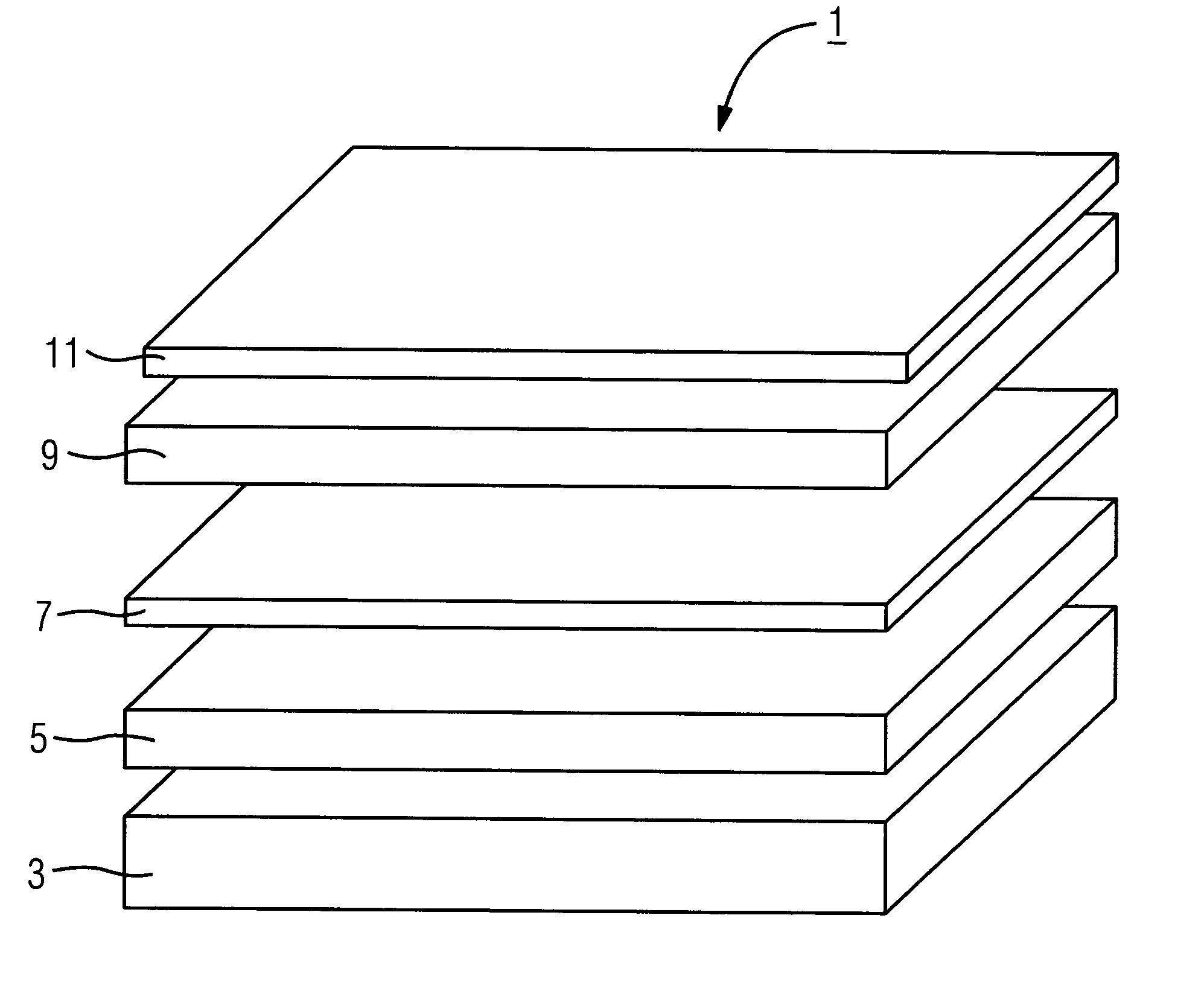
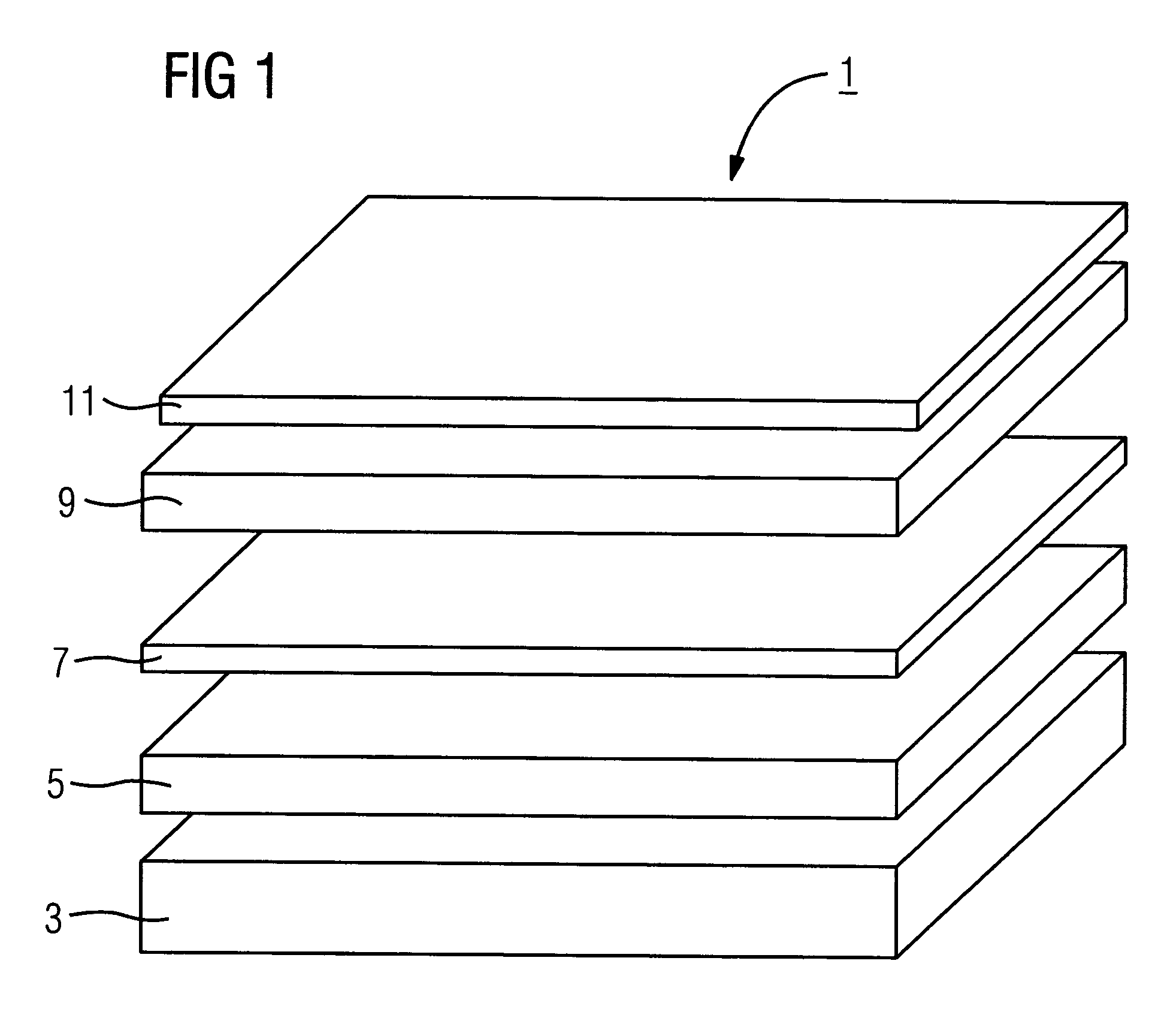
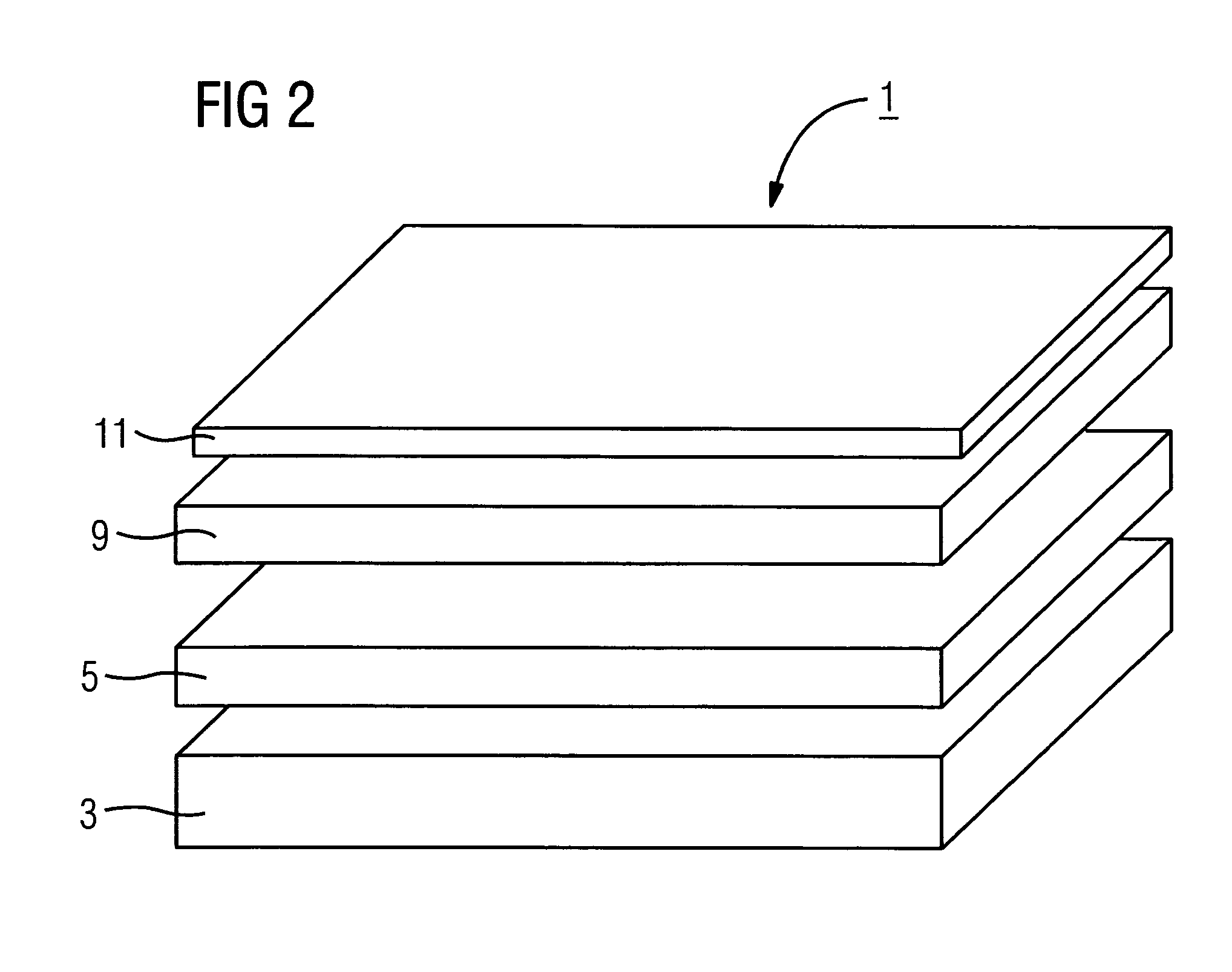
[0019]FIG. 1 shows the layer structure of an X-ray detector 1 for a CT device with an intermediate layer 7. For the sake of clarity, the layers are illustrated spaced apart from one another, but in reality are to be in direct contact with one another. Thus, in particular, the layers are not inherently rigid and can therefore bear optimally against one another. The layer structure is only diagrammatically illustrated. In particular, the figure does not illustrate any patterning or pixelation, since patterns of this type and the processes used to produce them do not form the subject of the present invention.

[0020]The layer structure is based on the combination of a phosphor layer 3 based on a ceramic scintillator material with a photodetector layer 9 based on an organic material.

[0021]Typical ceramic scintillator materials, e.g. Gd2O2S, CdWO4, etc., may be used for the phosphor layer 3. Scintillator materials of this type are mechanically stable. This property is exploited by virtue o...


PUM


Abstract

An X-ray detector is for a CT device and includes a phosphor layer for generating electromagnetic radiation as a function of the occurrence of X-radiation, and a photodetector layer for detecting the electromagnetic radiation generated by the phosphor layer. The phosphor layer includes ceramic material and the photodetector layer includes organic material. A process is further for producing an X-ray detector, including the steps of producing a phosphor layer from a ceramic material and applying a photodetector layer made from an organic material to the phosphor layer via a spinning, printing or beam / jet process or by sticking it on as a film. It is optionally possible to provide a further process step for polishing the surface of the phosphor layer before applying the photodetector layer.

Description

[0001]The present application hereby claims priority under 35 U.S.C. §119 on German patent application number DE 102 44 178.2 filed Sep. 23, 2002, the entire contents of which are hereby incorporated herein by reference.BACKGROUND OF THE INVENTION[0002]Electronic image detectors are increasingly being used in X-ray diagnostics. Whereas even nowadays in particular individual images are still frequently recorded using X-ray-sensitive film material, particularly in the case of series of X-ray pictures it is desirable to use electronic image detectors. These firstly allow faster image sequences to be taken, on account of the shorter exposure times required and the absence of mechanical film movement, and secondly allow the recorded data to be fed directly for electronic analysis. For example, in computer tomography (CT), series of thousands of individual images have to be combined to form an overall image, e.g. a tomogram.[0003]Electronic image detectors which are composed of a scintill...

Claims


Application Information

Patent Timeline
IPC IPC(8): G01T1/20G01T1/24G01T1/29H01L27/146
CPCG01T1/2018H01L27/14683H01L27/14676H01L27/1462H01L27/14625G01T1/20183
Inventor BRABEC, CHRISTOPHHEISMANN, BJOERNLEPPERT, JUERGENVON DER HAAR, THOMAS
Owner SIEMENS HEALTHCARE GMBH
Learn More