Method for measuring hematocrit value of blood sample, method for measuring concentration of analyte in blood sample, sensor chip and sensor unit
a technology of hematocrit and sensor chip, which is applied in the direction of liquid/fluent solid measurement, biomass after-treatment, enzymology, etc., can solve the problems of insufficient detection sensitivity of these sensor chips and inability to achieve stable hct measurement in the blood sampl
- Summary
- Abstract
- Description
- Claims
- Application Information
AI Technical Summary
Benefits of technology
Problems solved by technology
Method used
Image
Examples
example 1
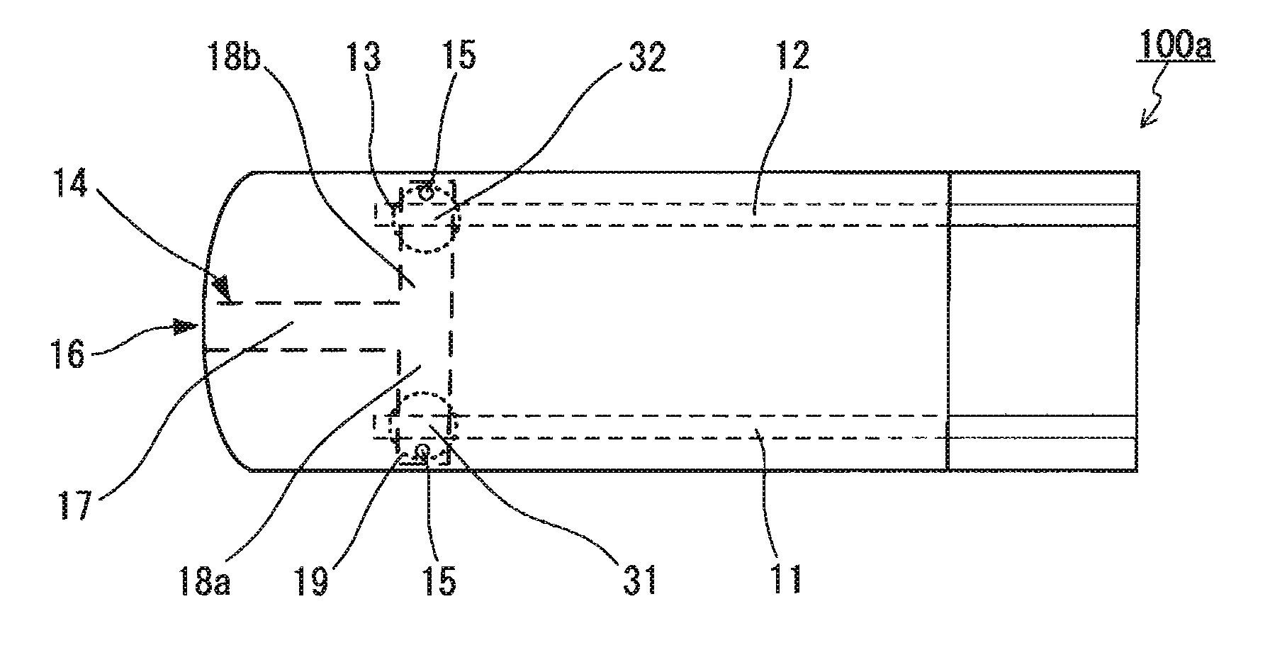
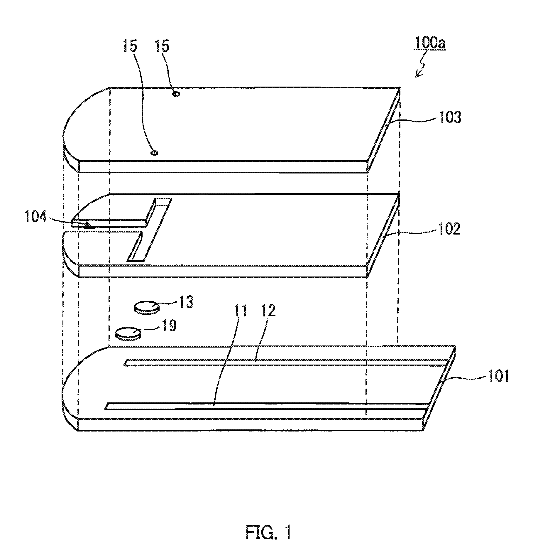
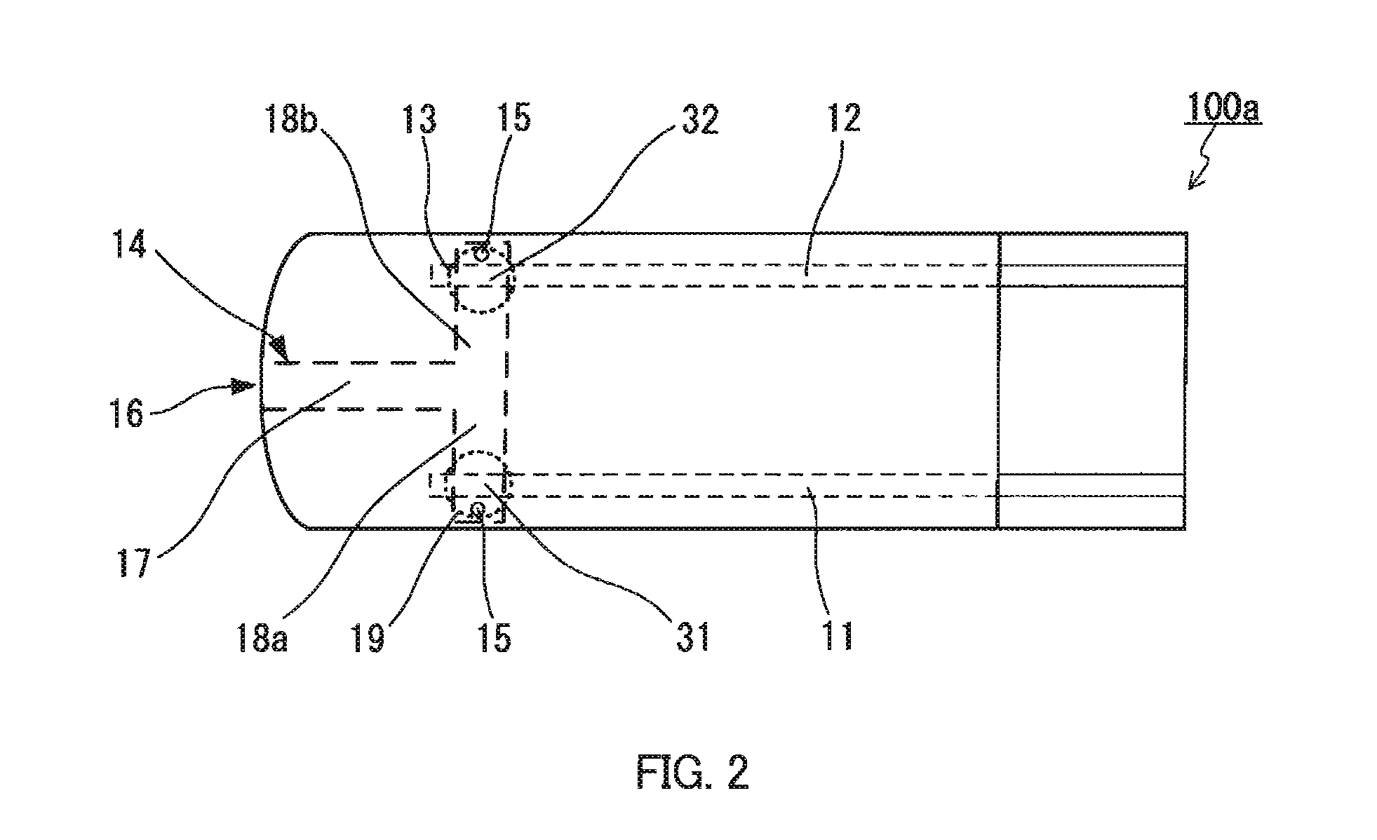
[0124]A sensor chip A for measuring a Hct value was prepared. Palladium was used as the electrode cores of the working electrode and the counter electrode. Using a spacer having a thickness of 100 μm, a 0.8 microliter (μL)-volume blood sample holder was formed. The effective areas of the working electrode and the counter electrode in the blood sample holder were 0.4 mm2 and 0.7 mm2, respectively, and the closest distance between the working electrode and the counter electrode was 2.4 mm. A reaction reagent layer A containing the reductant but not the oxidant of the redox substance was disposed to cover the surface of the working electrode facing the blood sample holder. A reaction reagent layer B containing the oxidant but not the reductant of the redox substance was disposed to cover the surface of the counter electrode facing the blood sample holder. The reaction reagent layer A was disposed on the surface by applying a reagent solution, prepared by dissolving 50 mM potassium ferr...
example 2
[0127]A sensor chip was prepared as in Example 1 except that the reaction reagent layer A was prepared using a regent solution that had been prepared by dissolving 50 mM potassium ferrocyanide and 1.0 mass % bovine serum albumin (SIGMA) in a 0.5 mass % CMC aqueous solution.
[0128]Each of the three kinds of blood samples was introduced into the blood sample holder of the sensor chip, and a voltage of 3.0 V or less was applied across the working electrode and the counter electrode serving as the anode and the cathode, respectively. A resulting response current flown between the working electrode and the counter electrode was measured. The results of measurement of response current are represented by the graphs shown in FIGS. 14 through 19. As shown in the graphs, the sensor chip of Example 2 was able to detect response currents reflecting the Hct values of the blood samples with a stable and distinct sensitivity difference, immediately after the application of a voltage of 3.0 V or les...
PUM
| Property | Measurement | Unit |
|---|---|---|
| voltage | aaaaa | aaaaa |
| voltage | aaaaa | aaaaa |
| voltage | aaaaa | aaaaa |
Abstract
Description
Claims
Application Information
 - R&D
- Intellectual Property
- Life Sciences
- Materials
- Tech Scout
- Unparalleled Data Quality
- Higher Quality Content
- 60% Fewer Hallucinations
Browse by: Latest US Patents, China's latest patents, Technical Efficacy Thesaurus, Application Domain, Technology Topic, Popular Technical Reports.
© 2025 PatSnap. All rights reserved.Legal|Privacy policy|Modern Slavery Act Transparency Statement|Sitemap|About US| Contact US: help@patsnap.com


