
Radiation analyzer and method for analyzing radiation

a radiation analyzer and radiation technology, applied in the direction of material analysis using wave/particle radiation, optical radiation measurement, instruments, etc., can solve the problems of difficult monitoring accurate baselines, difficult accurate determination of baselines, and inability to readily improve energy resolution to 130 ev or more, etc., to achieve high energy resolution

Active Publication Date: 2014-02-20
HITACHI HIGH TECH SCI CORP
View PDF1 Cites 20 Cited by
  • Summary
  • Abstract
  • Description
  • Claims
  • Application Information

AI Technical Summary

Benefits of technology

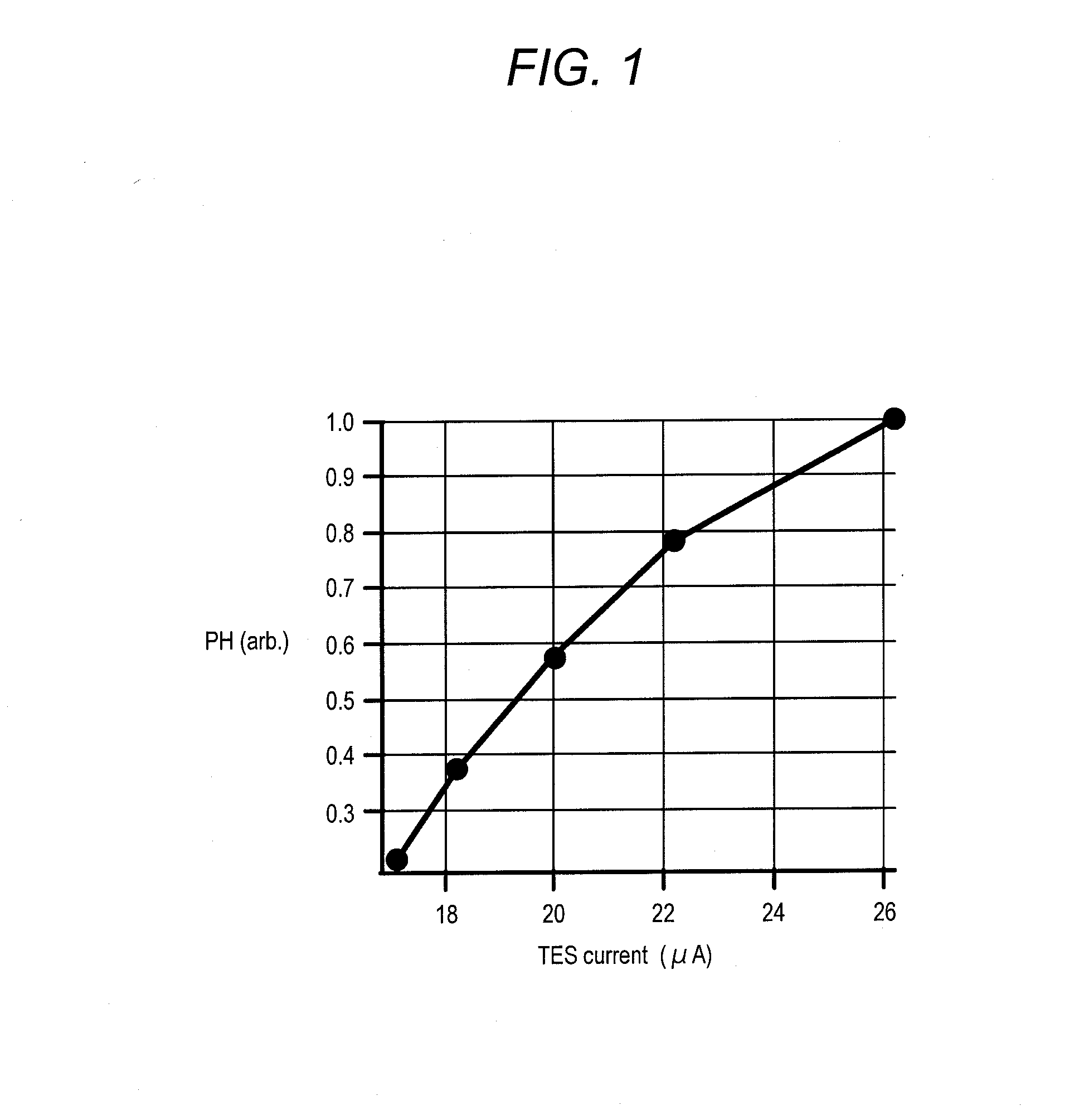
The present invention is a radiation analyzer and method for analyzing radiation that can accurately sensitivity correct even when the number of signal pulses is large, resulting in high energy resolution. The analyzer calculates and registers a correlation curve of a thermistor and a reference thermometer in advance, and uses information from the reference thermometer to correct the sensitivity of signal pulses. Even when the number of signal pulses is large, the analyzer can provide a constant peak value for a signal pulse in response to characteristic X-rays of the same energy. This allows for stable and high energy resolution over a long period of use. The sensitivity correction is performed regularly over time to obtain more accurate characteristics between the heater value and sensitivity. The analyzer contains a first and second heater for adjusting power values in the cryogenic temperature range, and the power of the first heater is adjusted through power adjustment of the second heater to facilitate more precise correction. The analyzer and method can correct sensitivity regardless of the counting rate of signal pulses, resulting in a constant peak value for a signal pulse in response to characteristic X-rays of the same energy.

Problems solved by technology

However, their energy resolution cannot be readily improved to 130 eV or more and remains merely one-tenth or less of that of WDSs.
By contrast, when the number of X-rays is large, a period between one pulse and the next one is short, that is, the period is not enough to detect a baseline, and thus it is hard to monitor accurate baselines.
Thus, there is a problem in that accurate determination of a baseline is difficult when a large number of signal pulses are detected.

Method used


Image

  • Radiation analyzer and method for analyzing radiation
  • Radiation analyzer and method for analyzing radiation
  • Radiation analyzer and method for analyzing radiation

Examples


Embodiment Construction

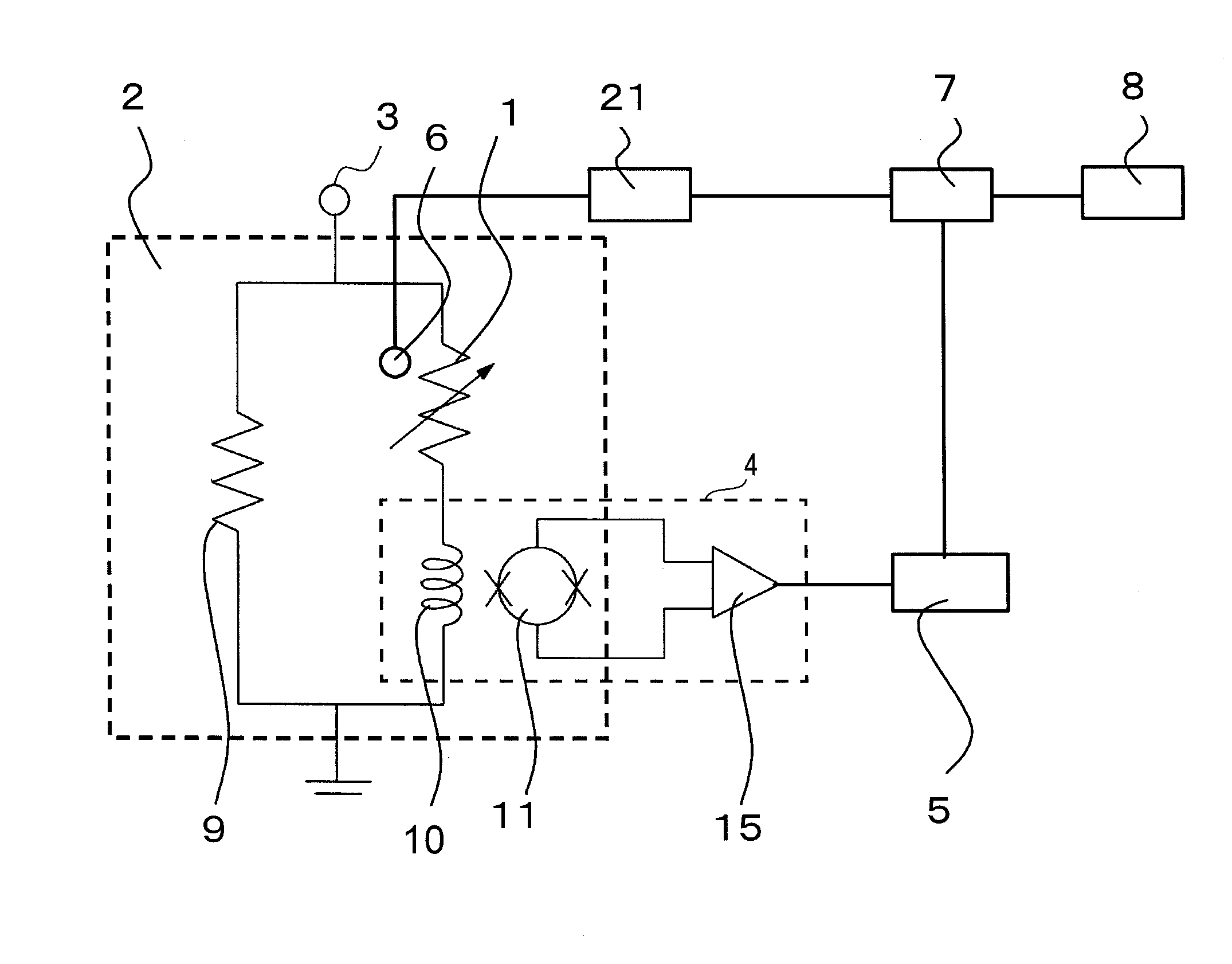
[0038]The following describes the operating principle of an embodiment of the present invention. In the operation of detecting radiation, a TES 1 utilizes a superconducting transition edge of a superconductor. The TES 1 holds an operating point in the superconducting transition edge between normal conductivity and superconductivity. Thus, in the case where the TES 1 absorbs radiation once and holds the operating point in the superconducting transition edge, the resistance change of several micro watts can be obtained with a temperature change of 100 mK, obtaining a radiation pulse in the order of micro angstrom.

[0039]The relation between a pulse peak value and radiation energy is obtained in advance. That makes it possible to detect the energy of radiation applied to the TES 1 based on the peak value of the signal pulse even if the energy of the radiation is unknown.

[0040]The operating point of the TES 1 is determined in accordance with a thermal balance between a current flowing in...


PUM


Abstract

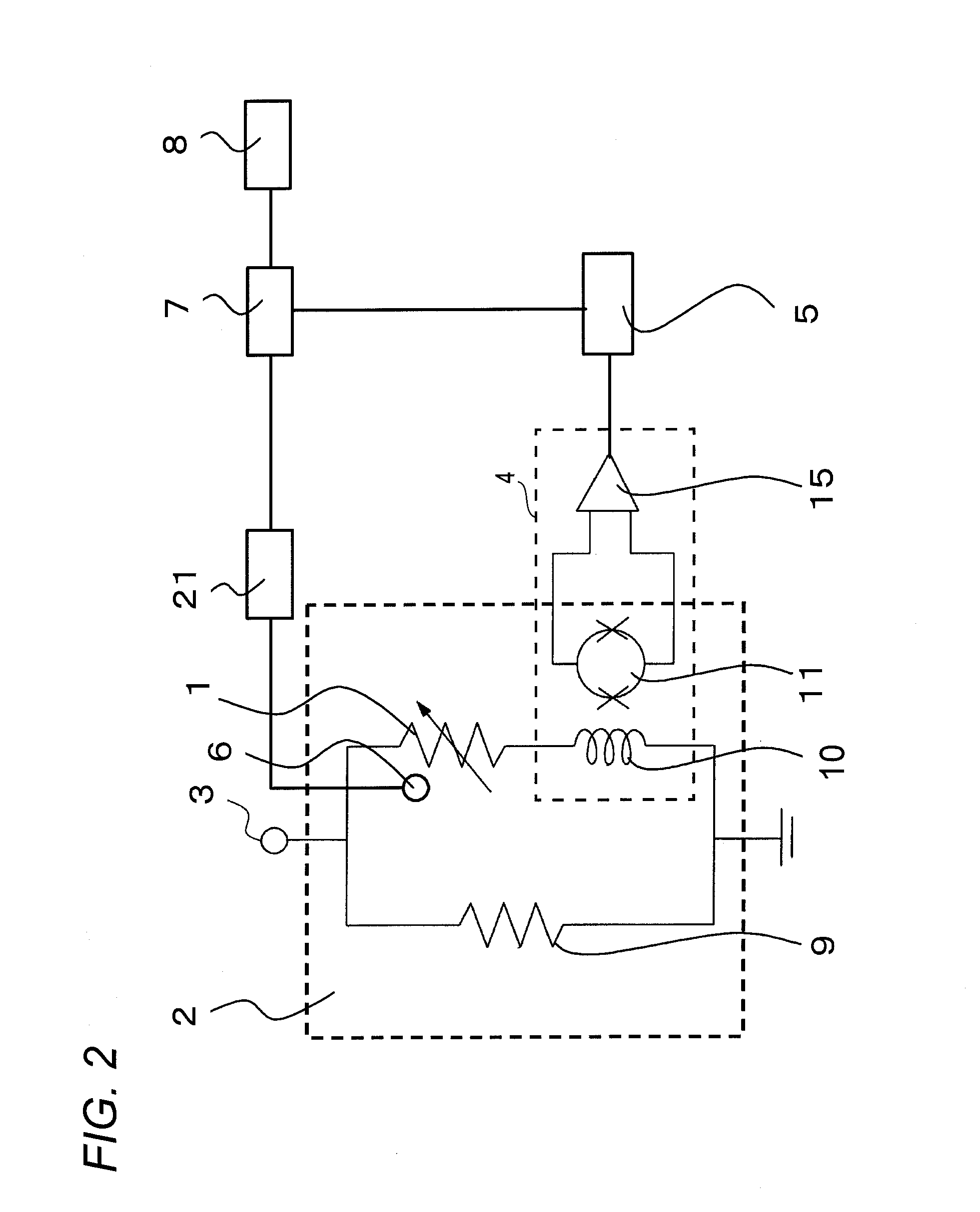
A radiation analyzer includes: a transition edge sensor (TES) that detects radiation; a current detection mechanism that detects a current flowing in the TES; a peak analyzing unit that measures a peak value based on the current detected by the current detection mechanism; a first heater that heats the TES to keep a constant temperature; a sensitivity correction operating unit that corrects sensitivity of the TES based on a relation obtained in advance between an output of the first heater and a peak value measured by the peak analyzing unit.

Description

[0001]This application claims priority from Japanese Patent Application No. 2012-181833 filed on Aug. 20, 2012, the entire subject-matter of which is incorporated herein by reference.BACKGROUND[0002]1. Technical Field[0003]The present invention relates to a radiation analyzer including a radiation detector provided with a transition edge sensor and to a method for analyzing radiation.[0004]2. Related Art[0005]There are radiation analyzers capable of energy discrimination of radiation such as an energy dispersive spectroscopy (EDS) and a wavelength dispersive spectroscopy (WDS).[0006]The EDS is an X-ray detector that converts the energy of X-rays captured therein to an electric signal and derives the energy depending on the intensity of the electric signal. The WDS is an X-ray detector that monochromatizes X-rays (energy discrimination) with a spectroscope and detects the monochromat zed X-rays with a proportional counter tube.[0007]Semiconductor detectors such as a silicon-lithium (...

Claims


Application Information

Patent Timeline
IPC IPC(8): G01T1/16
CPCG01T1/16G01T1/1606G01N23/225G01T1/26
Inventor TANAKA, KEIICHIOHGAKI, MASATAKAODAWARA, AKIKAZU
Owner HITACHI HIGH TECH SCI CORP
Learn More