
Machinable ceramic

a technology of machined ceramics and ceramics, applied in the field of machined ceramics, can solve the problems of reducing the value of a commercial product made from materials, difficult to machine most ceramic materials, and materials with high strength, and achieve the effect of low reflectivity and good machinability

Active Publication Date: 2007-01-09
FERROTEC CERAMICS CORP
View PDF16 Cites 8 Cited by
  • Summary
  • Abstract
  • Description
  • Claims
  • Application Information

AI Technical Summary

Benefits of technology

"The present invention provides a high-strength machinable ceramic with a strength of 240 MPa and good machinability. The ceramic has a coefficient of thermal expansion close to silicon and can be used for fine or high-precision machining on a micron level. The ceramic has a blackish color and is effective for use in probe guides and similar equipment. The main constituent of the ceramic is a combination of boron nitride, zirconia, and optionally silicon nitride, with a coloring additive. The ceramic can be produced by mixing the main constituent with a sintering aid and machining it to the desired shape."

Problems solved by technology

However, most ceramics are difficult to machine.
However, there are few materials which have the combination of high strength and excellent machinability required for high-precision fine machining along with a coefficient of thermal expansion close to that of silicon.
In addition, the color of conventional machinable ceramics is not uniform, and thus they have a poor appearance which reduces the value of a commercial product made from the materials.
Moreover, these ceramics have a white or pale color with high reflectivity, which prevents accurate inspection and measurement by image processing of machined parts formed from the ceramics.
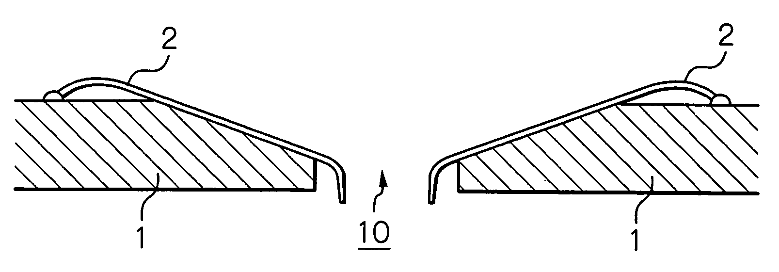
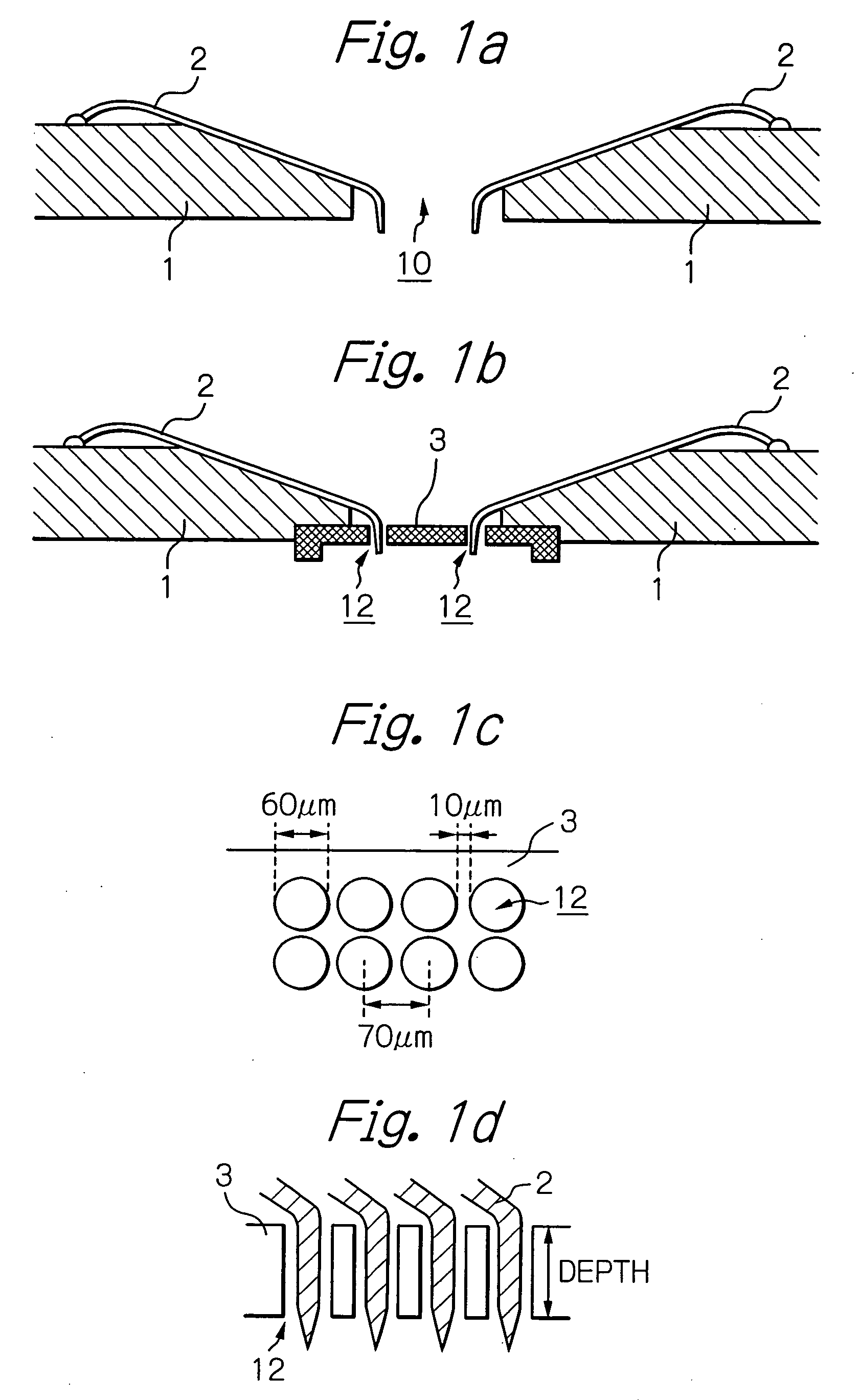
However, the probes are normally made of a slender metallic material, so they easily bend when the probe card 1 is pressed downwards, and due to the bending, it is easy for the positions of the tips of the probes 2 to slip.
As a result, it is difficult for the probes 2 to contact the electrode pads with certainty.
A plastic probe guide generally cannot be used for inspection at a high temperature.
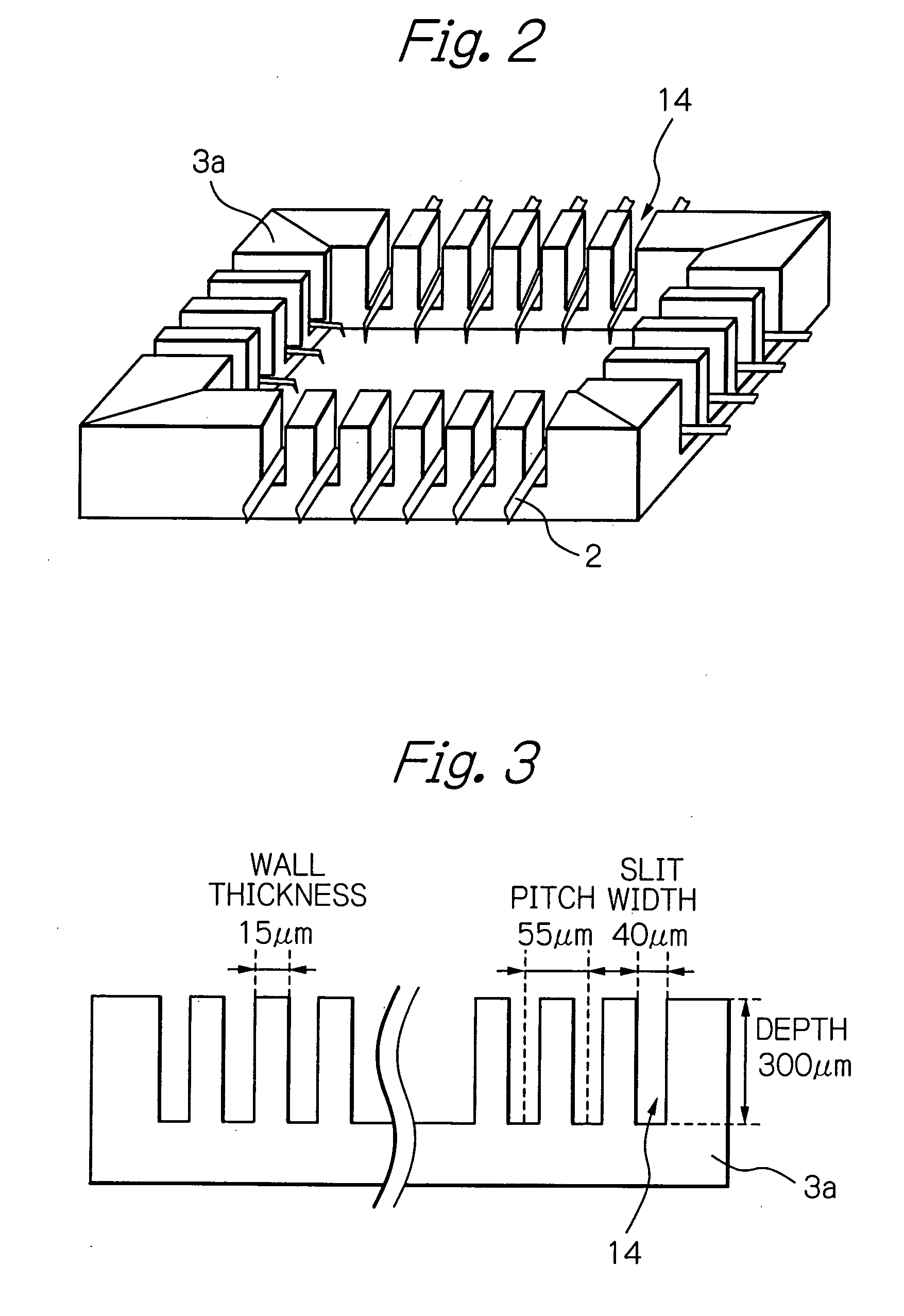
In addition, it is not possible to achieve sufficient dimensional accuracy of through holes or slits to inspect semiconductor elements of higher densities with smaller pitches of electrode pads.
However, the coefficient of thermal expansion of a crystallized glass ceramic is large compared to that of a semiconductor element, and depending upon the inspection temperature, positional deviation may occur between inspecting probes and the electrode pads of a semiconductor element being inspected.
In addition, the strength of a crystallized glass ceramic is not so high that chipping and cracking easily take place during drilling or other machining, and an adequate dimensional accuracy cannot be obtained.
Therefore, when image processing is carried out in order to inspect the dimensions of tiny through holes or slits formed in a probe guide or to perform positioning of a probe guide on a probe card, light is easily reflected from the ceramic surface of the probe guide, thereby making it difficult to obtain an accurate image.
In addition, due to the white color, dirt on exterior of the ceramic easily stands out and decreases the value of a product manufactured from the ceramic.
However, the machinability of this material is poor, so it is not suitable for high precision fine machining.
In addition, it has an irregular coloring which reduces the value of a product made from it.
Thus, when it is used in a jig for inspecting semiconductors such as a probe guide, depending upon the inspection temperature, positional deviations easily occur.

Method used


Image

  • Machinable ceramic
  • Machinable ceramic
  • Machinable ceramic

Examples


examples

[0073]The following examples illustrate the present invention with no intention of limiting it. In the following description, unless otherwise specified, % means mass % and parts means parts by mass.

examples 1 – 8

Examples 1–8

[0074]Powder of hexagonal boron nitride (h-BN) with an average particle diameter of 0.9 micrometers and a purity of 99%, zirconia powder with an average particle diameter of 0.1 micrometers, and optionally silicon nitride powder with an average particle diameter of 0.1 micrometers were mixed in the proportions shown in Table 1 to prepare a main constituent raw material powder. A sintering aid consisting of 2% of alumina and 6% of yttria based on the main constituent raw material powder was added to the main constituent raw material powder and mixed therewith in a wet ball mill using ethyl alcohol as a solvent. The ball mill had a polyethylene pot, and zirconia balls were used as a mixing medium. The resulting slurry was dried in a vacuum evaporator to obtain a raw material powder.

[0075]A graphite die was filled with the raw material powder, and hot press sintering was carried out at 1600° C. for 2 hours while applying a pressure of 30 MPa in a nitrogen atmosphere to obta...

example 9

[0083]Powder of hexagonal boron nitride (h-BN) having an average particle diameter of 0.9 micrometers and a purity of 99%, and zirconia powder having an average particle diameter of 0.8 micrometers were mixed in the proportions shown in Table 1. A sintered body was prepared and the resulting sintered body was tested in the same manner as described in Examples 1–8. The results are also shown in Table 1. A decrease in bending strength compared to the previous examples was observed.


PUM

PropertyMeasurementUnit
mass %aaaaaaaaaa
particle diameteraaaaaaaaaa
mass %aaaaaaaaaa

Abstract

A high-strength machinable ceramic capable of high-precision fine machining has a coefficient of thermal expansion close to that of silicon and preferably a uniform blackish color which facilitates image processing of machined parts. The ceramic comprises a main constituent and a sintering aid. The main constituent comprises 30–59.95 mass % of boron nitride, 40–69.95 mass % of zirconia, optionally up to 20 mass % of silicon nitride and 0.05–2.5 mass % (calculated as an element) of at least one coloring additive, which is selected from C, Si, elements of Groups IIIA–IVB in the fourth period, elements of Groups IVA–VB in the fifth period, elements of Groups IVA–VIB in the sixth period of the long form periodic table, and compounds of these elements.

Description

TECHNICAL FIELD[0001]The present invention relates to a machinable ceramic and particularly to a high-strength machinable ceramic which can be uniformly colored so as to have low optical reflectivity and which has a coefficient of thermal expansion which can be controlled to be in a desired range depending on the intended use. The present invention also relates to a method for the production of such a machinable ceramic and a machined part, such as a probe guide, which is manufactured from such a ceramic by machining such as cutting, grinding, and / or drilling.BACKGROUND ART[0002]In general, ceramics have excellent mechanical and electrically insulating properties as well as excellent high-temperature characteristics, and they have attracted attention as materials for use as parts of equipment for manufacturing semiconductors. Due to a large amount of shrinkage during sintering to produce a ceramic, such parts must be manufactured from a sintered body by machining such as grinding in...

Claims


Application Information

Patent Timeline
Patent Type & Authority Patents(United States)
IPC IPC(8): C04B35/583C04B35/488C04B35/5835C04B35/48C04B35/119C04B35/593C04B35/596C04B35/645
CPCC04B35/488C04B35/6261C04B35/62625C04B35/6455C04B35/583C04B2235/9661C04B2235/3217C04B2235/3225C04B2235/3232C04B2235/3239C04B2235/3241C04B2235/3244C04B2235/3251C04B2235/3262C04B2235/3272C04B2235/3275C04B2235/3281C04B2235/3284C04B2235/3286C04B2235/3291C04B2235/3293C04B2235/3826C04B2235/3843C04B2235/3847C04B2235/386C04B2235/3873C04B2235/405C04B2235/422C04B2235/5436C04B2235/5445C04B2235/767C04B2235/96C04B2235/9607C04B2235/963C04B35/48
Inventor ETOH, SHUNICHIYOSHITOMI, YASUKIARAHORI, TADAHISANAKAGAWA, KUNIAKIMORI, KAZUMASA
Owner FERROTEC CERAMICS CORP
Learn More