Conjoined reactor system

Inactive Publication Date: 2006-11-14
CONOCOPHILLIPS CO
View PDF10 Cites 1 Cited by
  • Summary
  • Abstract
  • Description
  • Claims
  • Application Information

AI Technical Summary

Benefits of technology

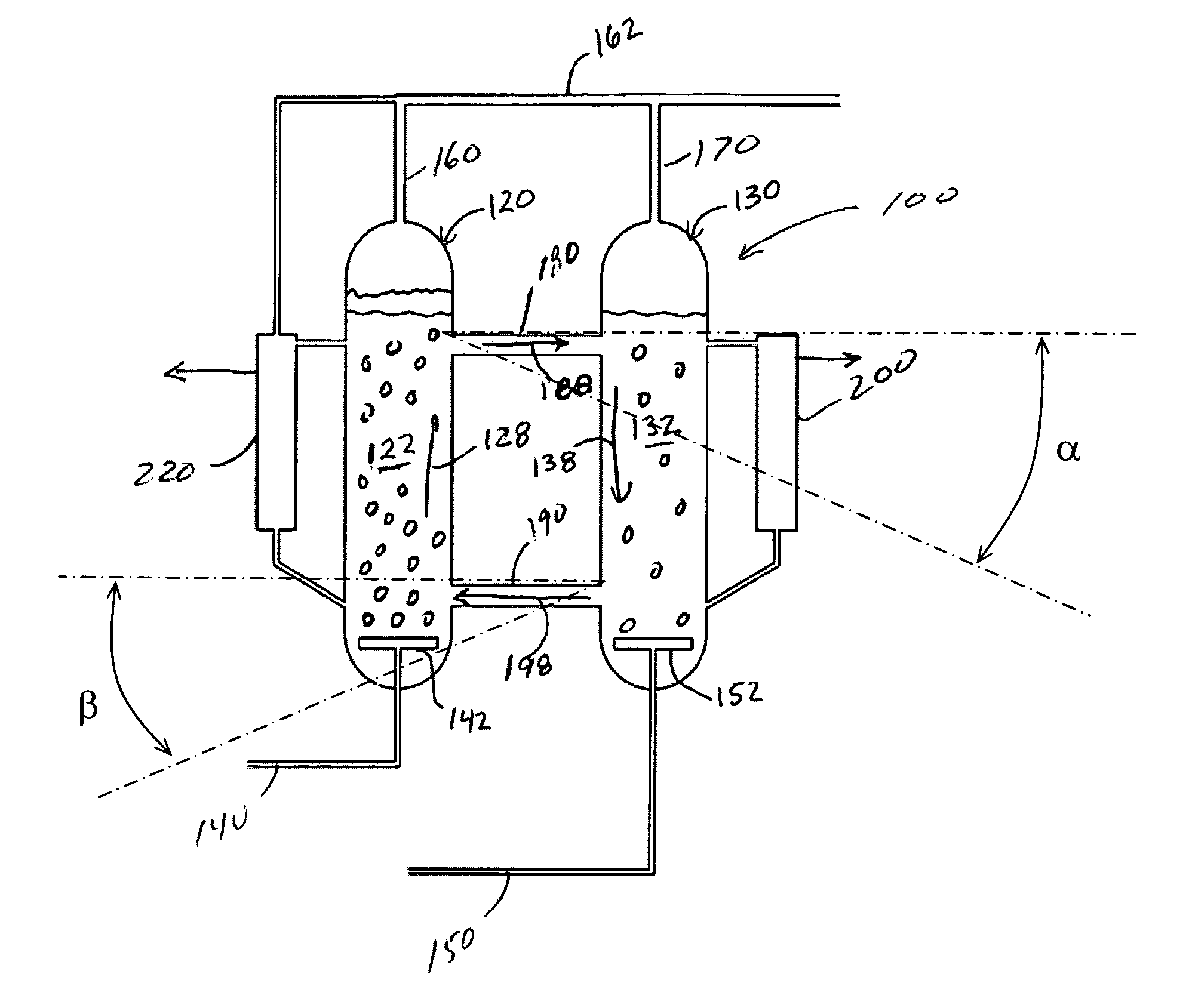
[0019]Regardless of the configuration of the reaction zones, by feeding gas into one of the reaction zones at a greater rate than into the second reaction zone, the volume fraction of gas in the first reaction zone, known as the gas holdup, can be made greater than the gas holdup in the second reaction zone. The difference in gas holdup values, in turn, causes a difference in slurry density between the two reaction zones. Because the slurry beds are approximately at the same height, the difference in slurry density will result in the hydrostatic pressure at the bottom of the second reaction zone being greater than the hydrostatic pressure at the bottom of the first reaction zone. This difference in hydrostatic pressures will cause fluid at the bottom of the second reaction zone to flow into the bottom of the first reaction zone. Finally, fluid leveling between the two reaction zones will cause fluid at the top of the first reaction zone to flow into the top of the second reaction zone. By controlling the flow rates of gas through the two reaction zones and of fluid between the reaction zones, the hydrodynamic behavior of such reactor system and the reactor performance are improved compared to those of a conventional gas-agitated slurry bed reactor.
[0021]Hence, a preferred embodiment of the present invention provides a method for the synthesis of hydrocarbons using solid catalysts in a three-phase reactor that gives high catalyst productivity and reactor capacity. The invention provides a design and method for operating a gas-agitated multiphase reactor system comprising two reaction zones, in which the difference in gas superficial velocities is between about 2 to about 45 cm / s. In accordance with various preferred embodiments, the present reactor system comprises at least one reactor stage with recycle or multiple reactor stages, with water stripping and catalyst / wax separation units shared between pairs or groups of reaction zones.
[0022]The present invention provides a novel gas-agitated reactor apparatus for gas-liquid or gas-solid multiphase synthesis comprising two reaction zones of relatively similar heights that are in fluid communication with each other achieved by at least one pair of fluid flow passages that allow a circulation of fluid between the reaction zones. The fluid circulation results in a more uniform distribution of the solids concentration (when applicable), and / or a more even temperature distribution along the axial direction. Additionally the fluid circulation between the two vessels introduces a forced convection, and hence increases the heat transfer coefficient and reduces the heat transfer surface area necessary for either heating or cooling.
[0023]Thus, the present invention provides a gas-agitated multiphase reactor system that is effective for enhancing reactor productivity and improving temperature control. For a synthesis using a catalyst as a solid phase, and having reactant(s) and product(s) in gas / liquid phases, this conjoined gas-agitated reactor system minimizes the difference in axial catalyst concentration and in particular for a Fischer-Tropsch synthesis, it lowers the maximum local water concentration therefore lowering catalyst deactivation rate.

Problems solved by technology

Wells that provide natural gas are often remote from locations with a demand for the consumption of the natural gas.
This transportation presents technological challenges due in part to the large volume occupied by a gas.
However, this contributes to the final cost of the natural gas.
Further, naturally occurring sources of crude oil used for liquid fuels such as gasoline, jet fuel, kerosene, and diesel fuel have been decreasing and supplies are not expected to meet demand in the coming years.
Therefore, the gas dispersion coefficient is also a complicated function of these design and operating parameters.
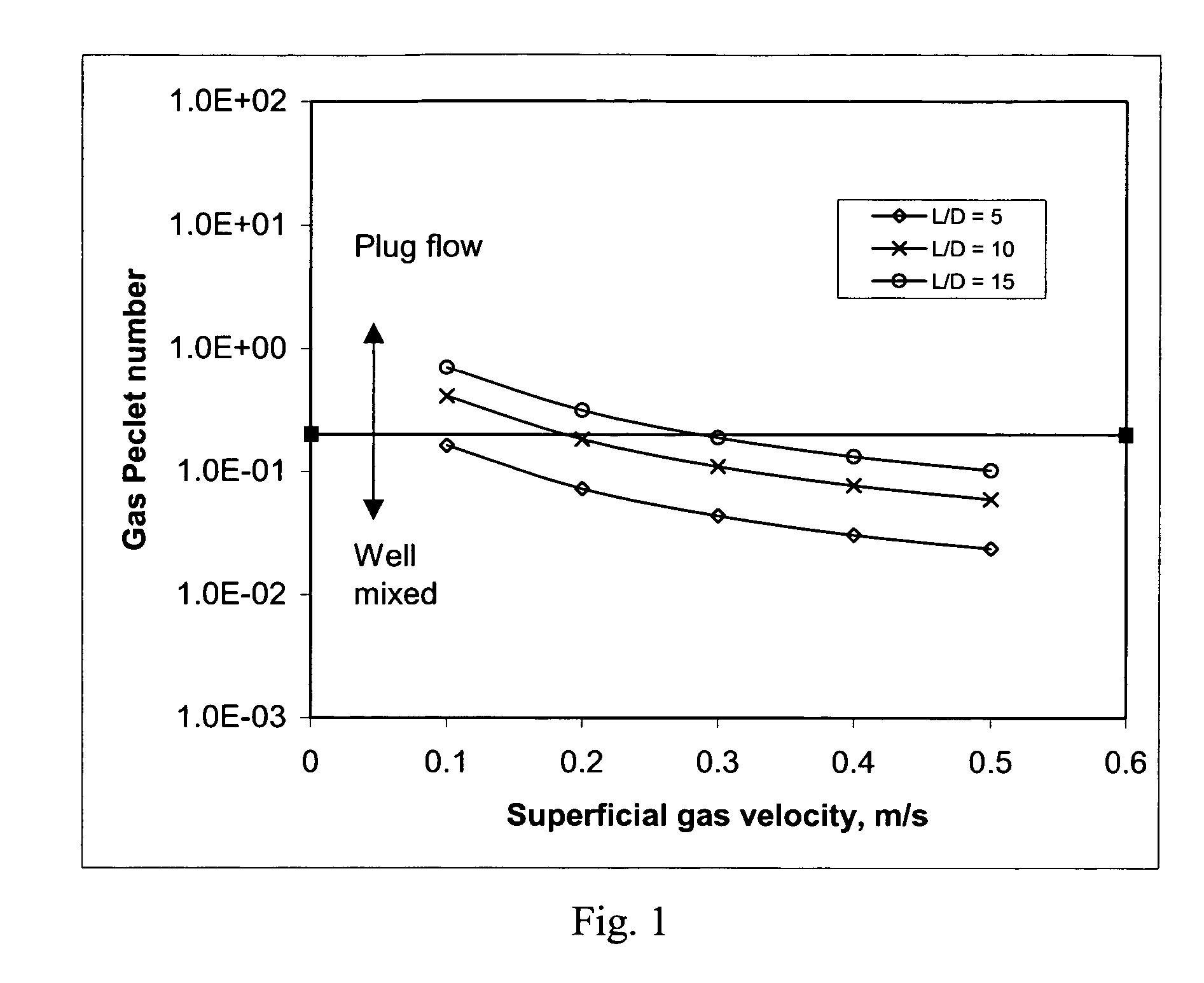
However the FT slurry bed reactors operating at conditions approaching plug flow regime typically are at low superficial gas velocities and tend to suffer from uneven distribution of the gas, liquid and solid phases and difficulty of temperature control.
This core-annular flow reduces the effective volume of the reactor because the entire reactor is not operating at the most efficient reaction conditions.

Method used


Image

  • Conjoined reactor system
  • Conjoined reactor system
  • Conjoined reactor system

Examples


examples

[0072]The following theoretical examples illustrate the principles and advantages of the present invention.

[0073]Conventional reactors were modeled at two superficial gas velocities and two temperatures. In addition, a reactor system embodying the present invention was modeled at similar operating conditions. Results of those simulations are given in Table 1 below. It can be seen that when the reactors are coupled in the manner described herein, a given catalyst system can be operated at a much higher productivity. Specifically, for a given maximum temperature of 223° C. (dependent on the catalyst composition and structure), reactors without liquid circulation have to be operated at an average temperature of 220° C. in order to ensure that no portion of the reactor experiences temperatures above the allowable maximum. At 220° C., the CO conversions are 49.5% and 72.4% for the inlet superficial gas velocities of 0.3 and 0.2 m / s, respectively. When these two reactors are conjoined, bo...


PUM

PropertyMeasurementUnit
Angleaaaaaaaaaa
Angleaaaaaaaaaa
Structureaaaaaaaaaa

Abstract

A gas-agitated multiphase reactor system with multiple reaction zones comprising gas-liquid or gas-liquid-solid mixtures that can maximize the production rate while allowing better control of the temperature distribution and better control of the liquid and solid phases in the reactors. Still more particularly, this invention relates to a method for operating a pair of linked gas-agitated slurry reaction zones such that the hydrodynamic behavior and reactor performance of such reactor system are improved compared to that of a conventional slurry bed reactor

Description

CROSS-REFERENCE TO RELATED APPLICATIONS[0001]This application is a divisional of U.S. patent application Ser. No. 10 / 444,459, filed May 23, 2003 now U.S. Pat. No. 6,800,664, and entitled “Conjoined Reactor System,” which is incorporated herein by reference.STATEMENT REGARDING FEDERALLY SPONSORED RESEARCH OR DEVELOPMENT[0002]Not applicable.TECHNICAL FIELD OF THE INVENTION[0003]The present invention relates to a process for the preparation of hydrocarbons from is gas. More particularly, this invention relates to a gas-agitated multiphase reactor system multiple reaction zones comprising gas-liquid or gas-liquid-solid mixtures that can maximize the production rate while allowing better control of the temperature distribution and better control of the liquid and solid phases in the reactors. Still more particularly, this invention relates to a method for operating a pair of linked gas-agitated slurry bed reactors such that the hydrodynamic behavior and reactor performance of such reacto...

Claims


Application Information

Patent Timeline
IPC IPC(8): B01J8/08C07C1/00B01J8/04B01J8/18B01J8/22B01J10/00C07C27/00C07C27/26C10G2/00F25J
CPCB01J8/1809B01J8/228C10G2/342B01J2208/00548
Inventor ESPINOZA, RAFAEL L.ZHANG, JIANPINGMOHEDAS, SERGIO R.ORTEGA, JR., JAMES D.
Owner CONOCOPHILLIPS CO
Why Eureka
Try Eureka