
Optical devices and methods employing nanoparticles, microcavities, and semicontinuous metal films

a technology of semi-continuous metal films and optical devices, applied in the field of optical devices and methods employing nanoparticles, microcavities, semi-continuous metal films, can solve the problems of large enhancement of optical emission, and achieve the effect of enhanced optical emission and enhanced optical emission of dye molecules

Inactive Publication Date: 2006-10-17
ARROWHEAD CENT
View PDF27 Cites 70 Cited by
  • Summary
  • Abstract
  • Description
  • Claims
  • Application Information

AI Technical Summary

Benefits of technology

[0065]A primary advantage of the present invention is the observed enhanced optical emission and lasing of molecules, or nanoparticles, placed on or near fractals located within or on a surface of a microcavity.
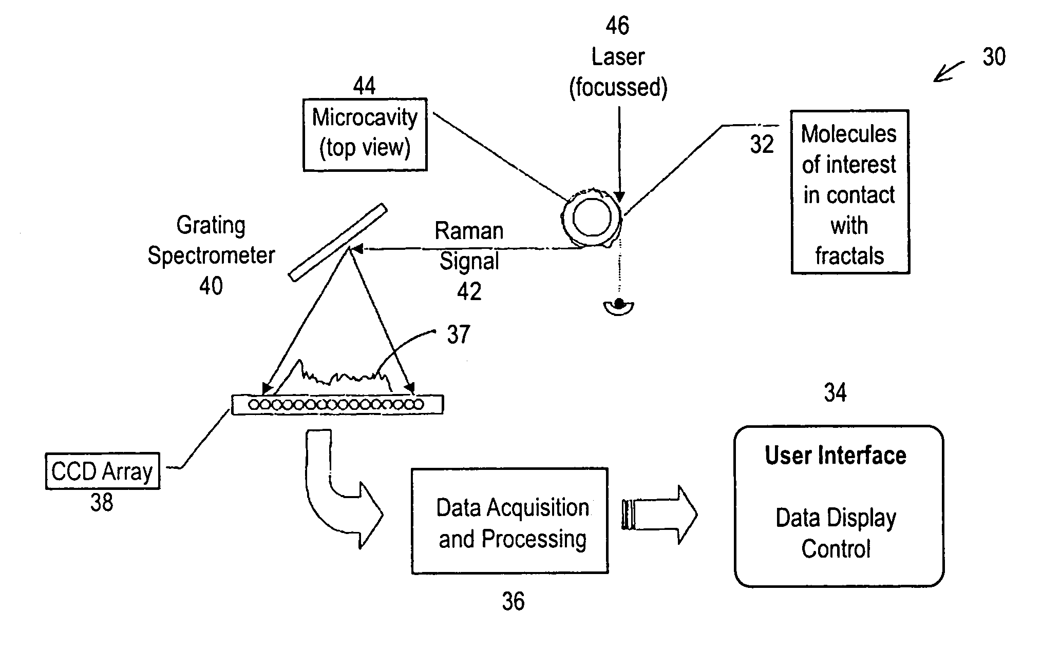
[0066]Another advantage of the present invention is the observed surface-enhanced Raman scattering, and other linear and non-linear optical processes of molecules, or quantum dots, placed on or near fractals located within or on a surface of a microcavity.
[0067]Another advantage of the present invention is the enhanced optical emission of dye molecules placed on or near fractals located within or on a surface of a microcavity.

Problems solved by technology

As described briefly above fractal aggregates and resonating microcavities are known to cause large enhancements of optical emissions.

Method used


Image

  • Optical devices and methods employing nanoparticles, microcavities, and semicontinuous metal films
  • Optical devices and methods employing nanoparticles, microcavities, and semicontinuous metal films
  • Optical devices and methods employing nanoparticles, microcavities, and semicontinuous metal films

Examples


example 1

LIDAR

[0171]Light detection and ranging (LIDAR) systems are versatile optical instruments that are currently used in a variety of atmospheric applications. LIDARs may be used to obtain: concentrations of a variety of atmospheric constituents such as chemical compounds, dust, volcanic ash, and water vapor; wind velocity and atmospheric turbulence profiles; and ultra-precise geodesy information. All LIDARs operate in a similar manner; a light source, usually a laser, is directed into the atmosphere through transmitter optics such as an optical telescope where it interacts with the atmospheric constituents. Some of the light produced by this interaction is collected by an optical receiver (typically, the transmitter telescope itself where, for some applications, it is spectrally analyzed, and then input to an optical detector. Optical detectors used in LIDAR systems are typically solid-state photodetectors; although having fairly good optical gain, they are susceptible to noise both fro...

example 2

OPO

[0175]Optical parametric oscillators (OPOs) are useful laser devices that may be tuned in wavelength over a wide range, typically through the visible and near-infrared range. The OPO depends on the nonlinear optical characteristics of materials together with the resonant characteristics of optical cavities. A pump beam is input to a nonlinear optical crystal where it is separated into two beams, a signal beam and an idler beam, wherein the signal is at shorter wavelengths than the pump, and the idler is at longer wavelengths. Under any given operating conditions, the sum of the signal and idler frequencies equals the pump frequency. If the signal or idler beam is input to an optical cavity, the resulting output has all of the characteristics of ordinary laser emission.

[0176]To apply the present invention, the nonlinear crystal is replaced by the fractal medium, and the optical cavity is replaced by the microcavity. An incident pump beam excites the signal and idler waves are grea...

example 3

Optical Data Storage

[0178]Improvement in data storage capacity is of great importance in computer and video disk technology. Given the fact that the optical gain in fractal media is localized in sub-wavelength regions (hot spots) of the fractal, and different wavelengths are amplified in spatially distinct regions of the fractal, the present invention has further application in data storage technology. By irradiation of the fractal with polychromatic, i.e. multi-wavelength light, a distribution of hot spots is generated in the fractal with a different distribution generated for each wavelength. However, if the radiation at a given wavelength has an intensity greater than some threshold value, the so-called photomodification threshold, then the distribution of hot spots in the fractal medium associated with that wavelength becomes “photomodified.” This means that a particular distribution of nanoparticles comprising the fractal medium is physically altered. The consequences of this p...


PUM

PropertyMeasurementUnit
widthaaaaaaaaaa
widthaaaaaaaaaa
thicknessaaaaaaaaaa

Abstract

An optical sensing enhancing material (and corresponding method of making) comprising: a medium, the medium comprising a plurality of aggregated nanoparticles comprising fractals; and a microcavity, wherein the medium is located in a vicinity of the microcavity. Also an optical sensor and sensing method comprising: providing a doped medium, the medium comprising a plurality of aggregated nanoparticles comprising fractals, with the material; locating the doped medium in the vicinity of a microcavity; exciting the doped medium with a light source; and detecting light reflected from the doped medium. Also an optical sensing enhancing material comprising a medium, the medium comprising a semicontinuous metal film of randomly distributed metal particles and their clusters at approximately their percolation threshold. The medium preferably additionally comprises a microcavity / microresonator. Also devices and methods employing such material.

Description

CROSS-REFERENCE TO RELATED APPLICATIONS[0001]This application is a continuation-in-part of U.S. patent application Ser. No. 09 / 797,609, entitled “Sensors Employing Nanoparticles and Microcavities”, filed on Mar. 1, 2001, now U.S. Pat No. 6,781,690 which is a continuation-in-part application of U.S. patent application Ser. No. 09 / 572,721, entitled “Optical Enhancement with Nanoparticles and Microcavities”, filed on May 16, 2000 and issued as U.S. Pat. No. 6,608,716 on Aug. 19, 2003, which claims the benefit of the filing of U.S. Provisional patent application Ser. No. 60 / 134,564, entitled “Fractals in Microcavities: Giant Coupled, Multiplicative Enhancement of Optical Responses,” filed on May 17, 1999, and of U.S. Provisional patent application Ser. No. 60 / 190,863, entitled “Microcavity Enhanced Optical Processes and Fractal Enhanced Optical Processes,” filed on Mar. 20, 2000, and the specifications thereof are incorporated herein by reference.[0002]This application is also a continu...

Claims


Application Information

Patent Timeline
Patent Type & Authority Patents(United States)
IPC IPC(8): G01J3/44G01N21/65G02F1/35G02F1/355G02F1/37G02F1/39G11B7/0045H01S3/06H01S3/30
CPCB82Y10/00B82Y20/00G01J3/44G01N21/65G02F1/355G11B7/00453H01S3/0602H01S3/30G01N2021/655G02F1/353G02F1/3534G02F1/3536G02F1/3538G02F1/37G02F1/39G02F2202/36G02F2203/15
Inventor ARMSTRONG, ROBERT L.SHALAEV, VLADIMIR M.SMITH, HAROLD V.SARYCHEV, ANDREY K.YING, Z. CHARLES
Owner ARROWHEAD CENT
Learn More