Tri valve backflow preventer

a backflow prevention and valve technology, applied in valve housings, water supply installations, drawing-off water installations, etc., can solve the problems of affecting the safety of drinking water to be delivered to the public, affecting the safety of workers, draining into the working area, etc., to reduce the use of good water, reduce safety risks, and reduce man hours and equipment time

Inactive Publication Date: 2006-10-17
WALTER GUY ROBERT +1
View PDF2 Cites 8 Cited by
  • Summary
  • Abstract
  • Description
  • Claims
  • Application Information

AI Technical Summary

Benefits of technology

[0006]It is the primary object of this invention to provide additional valve means for use with a conventional temporary backflow prevention system for improved water main installation and upgrade as a result of reduced man hours and equipment time, reduced use of good water for flushing and testing purposes, and reduced safety risk for the drinking water provided to the public after installation. A further object of this invention is to provide additional valve means for improved water main installation and upgrade that can be used everywhere for new and repaired / upgraded water mains. It is also an object of this invention to provide additional valve means for improved water main installation and upgrade that is safe and practical, and results in the use of two less joints in the finished water main pipe. A further object of this invention is to provide additional valve means for improved water main installation and repair / upgrade that allows for the new water main pipe to be completely pressure tested and bacteria free after temporary backflow prevention system removal, and require no subsequent tie in procedure. It is also an object of this invention to provide additional valve means for improved water main installation and upgrade that allows for fire protection on the construction site at all times where a fire hydrant connection is installed. It is a further object of this invention is to provide additional valve means for improved water main installation and repair / upgrade that meets regulatory drinking water regulations and standards.

Problems solved by technology

However, use of a jumper system has many disadvantages, including potentially adverse affects on worker safety and / or the safety of the drinking water to be delivered to the public via the new or repaired / upgraded sections of water main pipe.
However, such an installation of a temporary backflow prevention system typically creates an approximate eight foot separation between the new / upgraded and existing sections of water main pipe that will ultimately need to be connected together after the temporary backflow prevention system is removed.
The problems begin to occur when the temporary backflow prevention system is removed, as all of the water in the new or upgraded sections of water main pipe used for its testing is lost, and then the new or upgraded water main pipe needs to be refilled, re-flushed, and successfully pass additional pressure and bacterial contamination testing prior to being used for drinking water delivery.
One important problem associated with the removal of the conventional temporary backflow prevention system just described is that the contractors performing the new main construction typically excavate back down to the whole area of the existing water main valve and the new or repaired / upgraded water main pipe, and then when the jumper system is removed, all of the water in the new or repaired / upgraded water main pipe that was used for its testing drains into the working hole.
This causes the waste of hundreds of gallons of good clean drinking water, and further leaves the existing valve and new or upgraded water main pipe open and exposed to the possible entry of bacteria, a procedure that defeats the pre-testing step of chlorinating the inside of the new or repaired / upgraded sections of water main pipe to make them bacteria-free.
Worker safety can also be compromised by the water drained into the excavation hole.
Further disadvantages of the commonly used jumper system involve the tie in of the new or upgraded water main pipe, which is completed by use of a retrained ductile iron sleeve to connect the new or repaired / upgraded water main pipe to the existing water main shut-off valve, followed by flushing of the new / upgraded / repaired water main pipe with water to remove all of the air therein.
The tie in takes extra inspection hours, extra man hours, extra equipment hours, extra material cost, wasted large amounts of good water, and even then there is no guarantee that the new water line is free of bacteria.

Method used


Image

  • Tri valve backflow preventer
  • Tri valve backflow preventer
  • Tri valve backflow preventer

Examples


Embodiment Construction

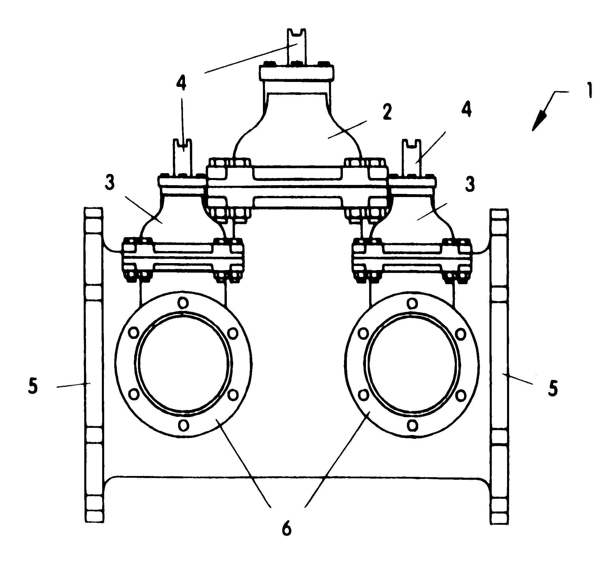
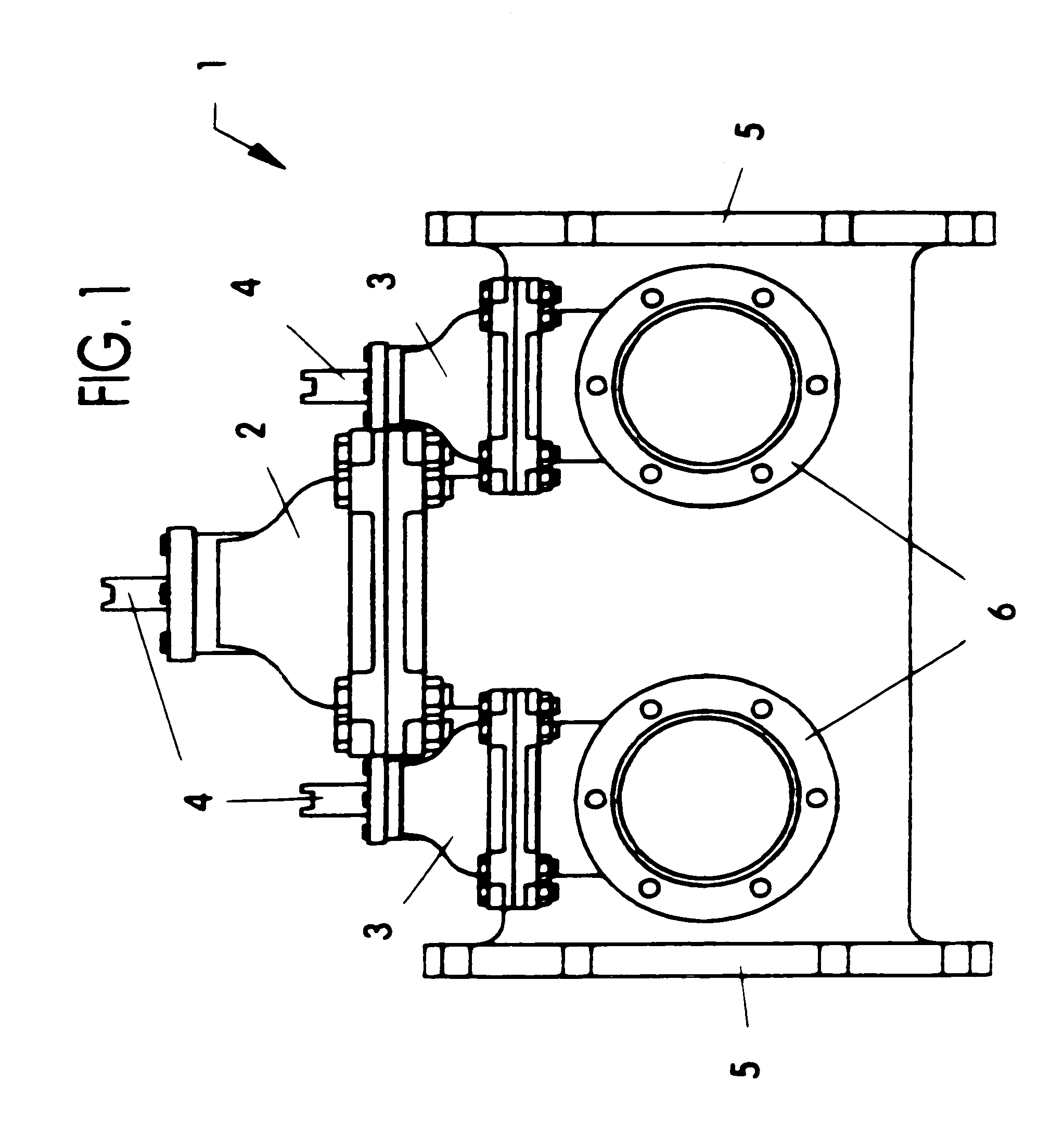
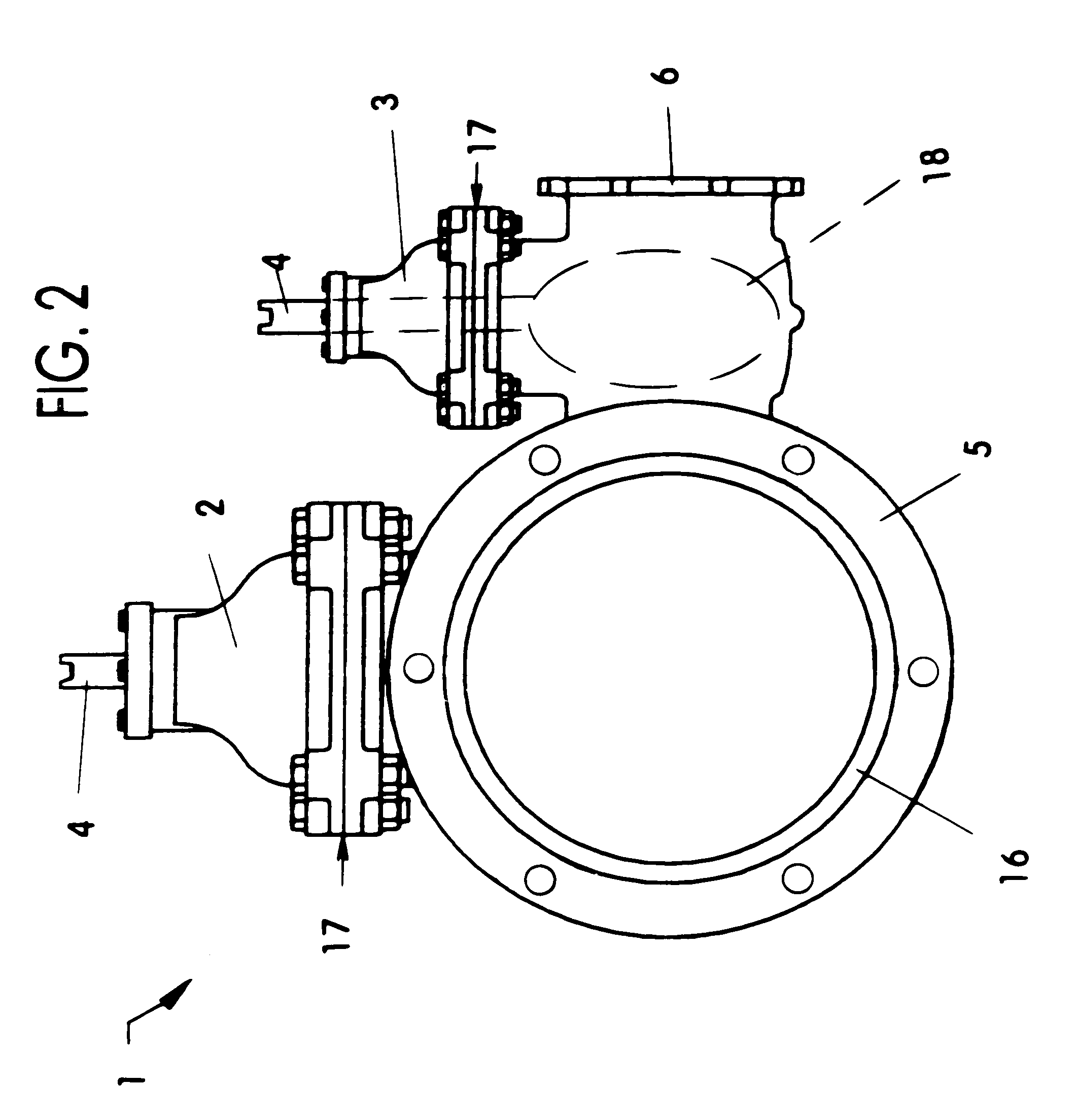
[0015]The present invention provides a tri valve 1 that is installed onto an existing potable water main pipe 7 by means of a tapping sleeve, a cut-in tee, an existing stub out, an existing valve, and / or similar means (not shown), at the beginning of construction to install a new section of water main pipe 8, or upgrade / repair an existing section of water main pipe, for future use by residential or commercial developments to satisfy potable water needs. For example, a contractor or utility company would excavate down to an existing 12-inch water main 7 with an existing 12-inch stub out tee, or install a 12-inch tapping saddle to core into an existing 12-inch potable water line 7. Thereafter, a 12-inch by 6-inch present invention tri valve 1 would be installed by whatever means are available to tie it in, as long as the tie in process is conducted in accordance with federal, state, and / or local standards or specifications. When tie in is complete, the 12-inch main valve gate 2 of the...


PUM

PropertyMeasurementUnit
diameteraaaaaaaaaa
diameteraaaaaaaaaa
diameteraaaaaaaaaa

Abstract

A tri valve backflow preventer having parts and materials preferably consisting of steel nuts and bolts, ductile iron operating nuts, nitrile rubber O-rings, nitrile rubber gaskets, manganese bronze valve adjusting stems, valve wedge gates made of ductile iron encapsulated with EPDM rubber, and ductile iron valve bodies. Material and parts are constructed in accordance with ASTM standards and the requirements of the AWWAC-509 and AWWAC-504 for gate valves and butterfly valves. The tri valve backflow preventer is used with a temporary conventional backflow assembly between existing water main pipe and new / upgraded sections of water main pipe while they are under construction. It is left in place when the temporary backflow assembly is removed. Its use saves extra inspection hours, extra man hours, extra equipment hours, conserves large amounts of good water otherwise needed for flushing, and reduces the safety risk to the public during activation of new water lines.

Description

BACKGROUND[0001]1. Field of the Invention[0002]This invention relates to the field of devices used to protect public drinking water during and after water main construction, specifically to a tri valve backflow prevention apparatus and a method of its use with a temporarily installed conventional backflow prevention assembly between existing water main pipe and a newly constructed, repaired, or upgraded section of water main pipe, to provide water needed at the construction site for pipe testing and other purposes. Its advantages relate to the temporary backflow prevention assembly being exclusively connected to it, and not to the water main pipe under construction, whereby when pressure and bacterial testing in the constructed pipe is successfully completed and the temporary assembly is removed after construction for use elsewhere, water is not drained from the constructed pipe, as in prior art methods of water main construction in common use today. Water draining into the construc...

Claims


Application Information

Patent Timeline
Patent Type & Authority Patents(United States)
IPC IPC(8): E03B7/07E03B1/02F16K11/20F16K27/00
CPCE03B7/077F16K27/006Y10T137/0402Y10T137/87338Y10T137/87555
Inventor WALTER, GUY ROBERTWALTER, GAIL PATRICIA
Owner WALTER GUY ROBERT
Why Eureka
Try Eureka