Dial gauge

A detector and detector head technology, applied in the field of detectors, can solve problems such as inconvenience in use, and achieve the effects of improving accuracy, shortening equipment time, and excellent economy.

Inactive Publication Date: 2009-07-15
HAFF & SCHNEIDER
View PDF4 Cites 0 Cited by
  • Summary
  • Abstract
  • Description
  • Claims
  • Application Information

AI Technical Summary

Problems solved by technology

Although they allow accurate readings, they have the disadvantage that they can only be read at rest, since the indicated value changes at a speed that is indistinguishable to the human eye during start-up
[0004] Therefore, these known devices have not proven to be convenient enough to use

Method used


Image

  • Dial gauge
  • Dial gauge
  • Dial gauge

Examples


Embodiment Construction

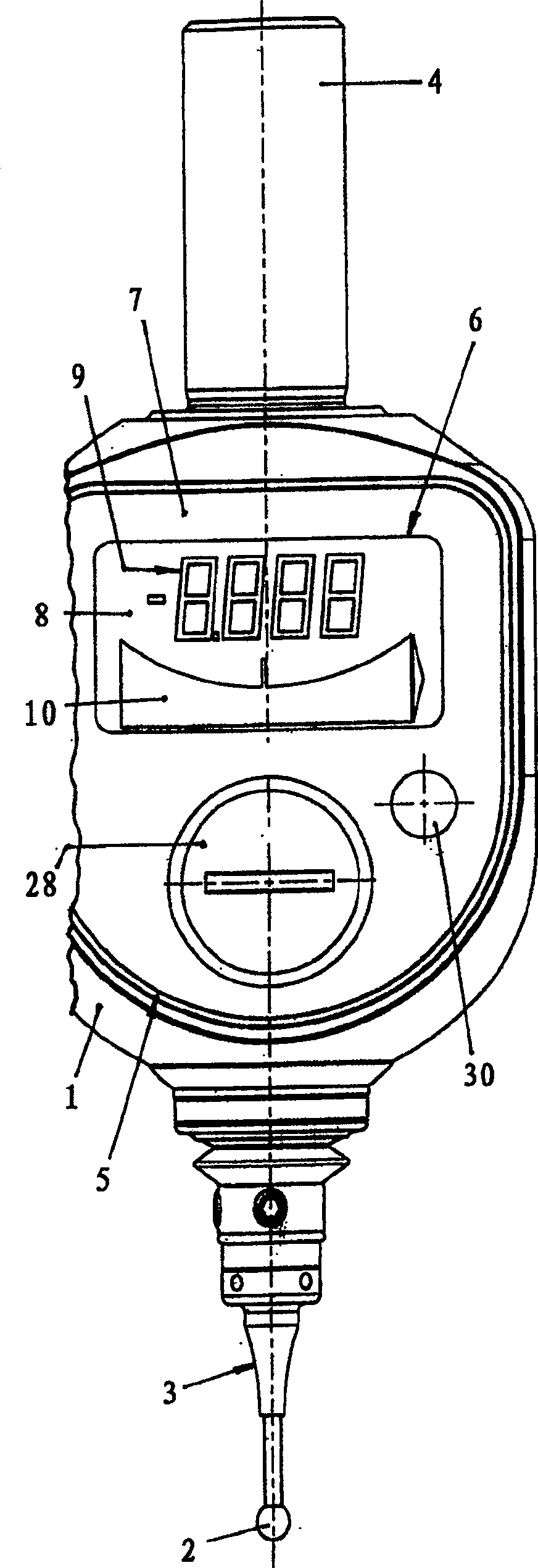
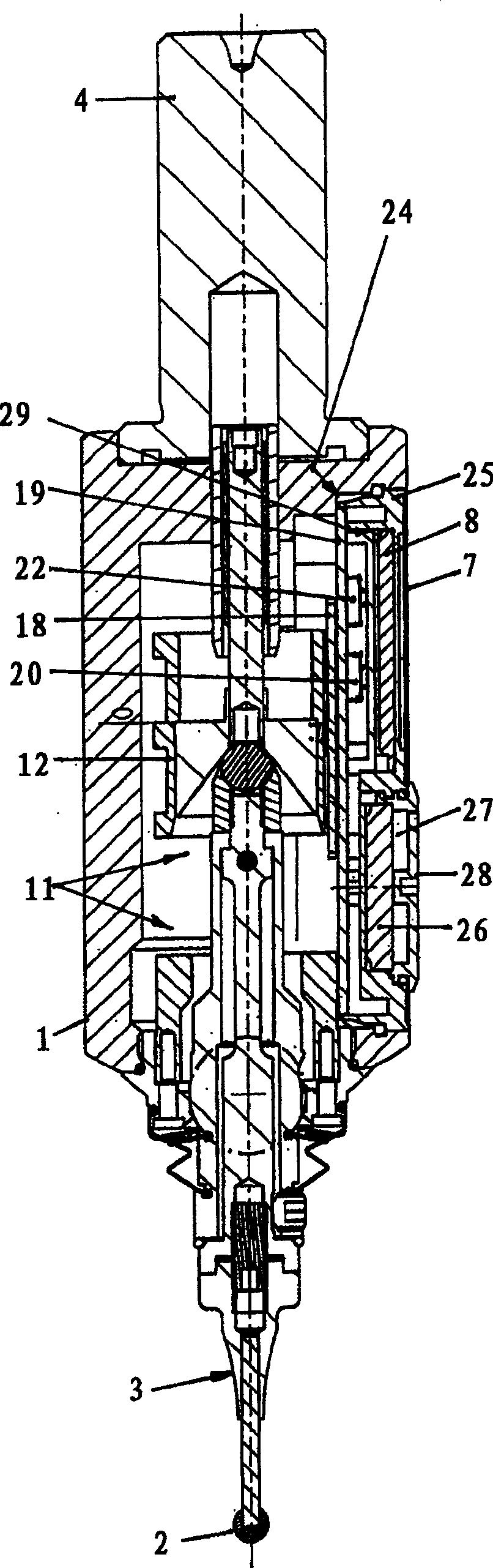
[0021] exist figure 1 and 2 The probe shown in has a probe head 3 protruding from a housing 1 and provided with a spherical probe 2 for probing a defined edge on a workpiece clamped in the workpiece chuck of a machine tool. The housing 1 is provided with a journal 4 for clamping the probe in the tool holder of the machine tool. The probe head 3 can be displaced radially and / or axially. In the illustrated embodiment, the probing head 3 is radially and axially deflectable, allowing three-dimensional probing of a workpiece.

[0022] In the region of the housing side facing the user, the housing 1 is formed with a window-like opening 5 in which a display 6 which can be read from the outside is located. The opening 5 is closed to the outside by a transparent cover 7, for example made of glass.

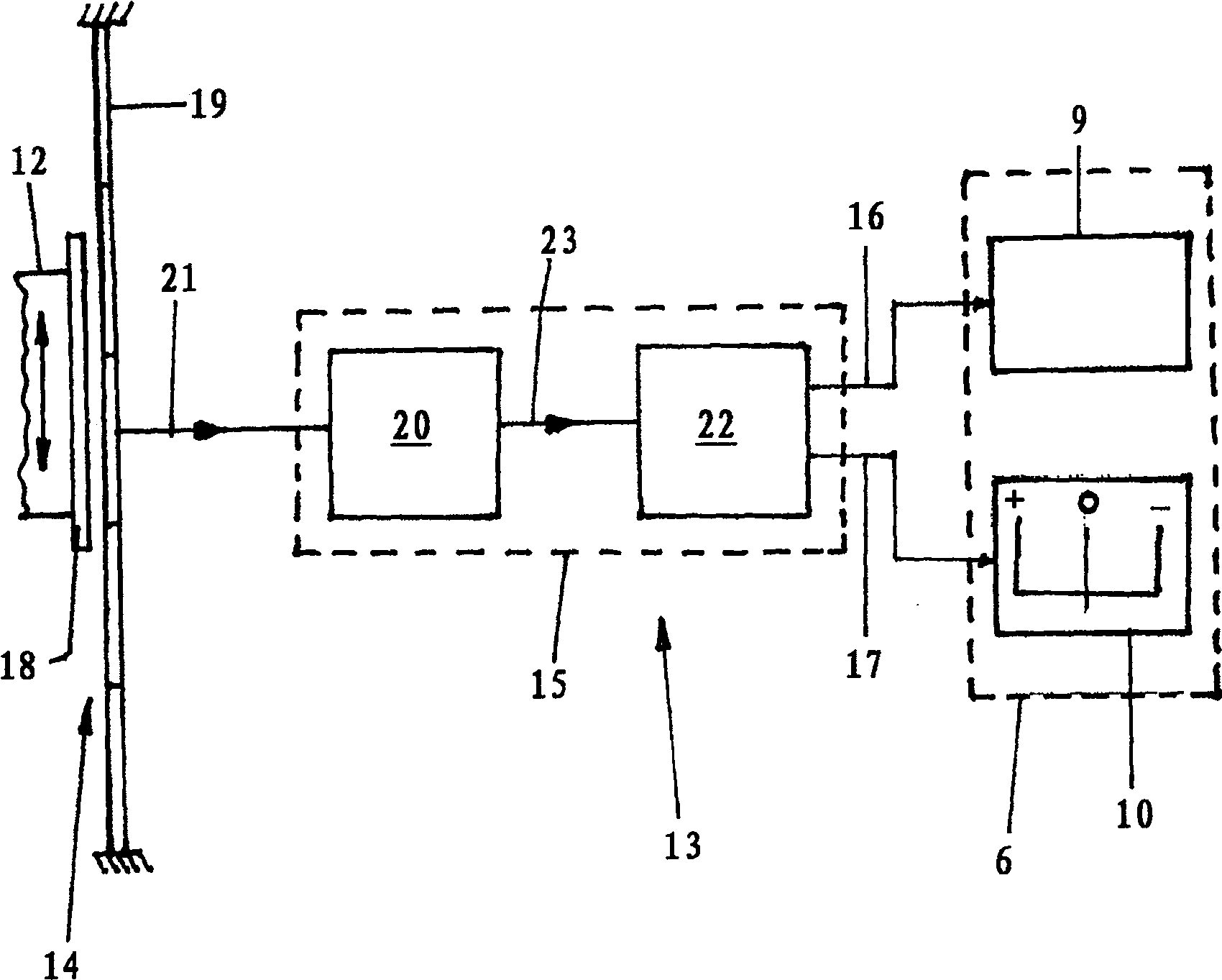
[0023] The display 6 is designed as a digital device and includes a display 8 on which two display lines arranged next to each other here one above the other are arranged. Among them, ...


PUM


Abstract

A display (6) includes a numerical display (9) and a graphical display (10), and is provided with an operating device including an electronic computer connected to a distance measuring device with two movable elements. One element is arranged on a slider, while the other is stationary. The resolution of the path covered by the slider increases on the graphic display as the probe head reaches the zero point.

Description

technical field [0001] The invention relates to a detector, especially for detecting workpieces in machine tools, which comprises a radially and / or axially deflectable probe head, the deflection of the probe head being converted into linear motion of a slide valve by means of a conversion system , the slide valve cooperates with a control device for the display. Background technique [0002] Such a tool is known from DE3701730C2. In this known device, the display is designed as an analog display, which has a number disc that cooperates with a movable pointer. The operating device is designed as a mechanism for manipulating the pointer. The disadvantage here is that empirically accurate reading of the pointer position has proven to be very difficult and that the person who reads the meter usually needs to be very close to the display device. In addition, reading an analog display may result in errors depending on, for example, the specific viewing angle of the person readi...

Claims


Application Information

Patent Timeline
Patent Type & Authority Patents(China)
IPC IPC(8): G01B5/012G01B5/00B23Q17/20G01B3/22G01D7/00
CPCG01B5/012G01B3/22G01D7/002
Inventor 弗里多林·默茨
Owner HAFF & SCHNEIDER
Why Eureka
Try Eureka